


Contents: 17.9.1. Gear rims for wheel speed ⇓ 17.9.2. Removing and installing…⇓ 17.9.3. Removing and installing the…⇓
The purpose of this repair manual is not to describe the operating principle of the unit, and therefore the following text concerns the removal and installation of parts that may be encountered during other work. This applies primarily to wheel speed sensors and wheel-mounted toothed rims. The toothed rims used to indicate wheel speed are mounted on the drive shaft at the front wheels and on the inside of the brake discs at the rear wheels. The corresponding work has already been described for the removal and installation of the named parts.
17.9.1. Gear rims for wheel speed
Gear rims used to indicate wheel speed are mounted on the drive shaft at the front wheels and on the inside of the brake discs at the rear wheels. The corresponding work on dismantling and installation of the specified parts has already been described.
17.9.2. Removing and installing front speed sensors
The left and right sensors cannot be confused, and for this reason, the supports are designated with the letters "L" or "P." Removal is carried out in accordance with the instructions in Figure 241.
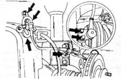
Figure 241. Arrows indicate the mounting locations of the front wheel speed sensors when the anti-lock braking system is installed.
All parts indicated by arrows must be released and the sensor removed from the steering knuckle. The wheel must be unscrewed.
When installing, tighten the bolts to 16-23 Nm. Pass the wiring harness through the mudguard and secure it with a clamp, then screw it in place with a lock washer.
After the plug has been inserted, tap the wheel on the right and left to check that the cable does not rub against the shock absorbers or the body.
17.9.3. Removing and installing the rear speed sensor
Removal of the rear sensor is carried out according to the instructions in Figure 242. The wheel must be unscrewed. The rear sensors should also be marked with the letters "L" and "P." When installing, place the sensor in the wheel hub support and tighten the bolts to 16-23 Nm. Tighten the wiring harness shield to the same torque. Pass the wiring harness through the body and press the rubber bushing.
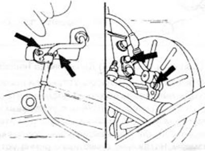
Figure 242. Arrows indicate the mounting locations of the rear wheel speed sensors when the anti-lock braking system is installed
Tighten the lock washer to 11-26 Nm. Finally, insert the plug and reinstall the wheel.
[Original material on the website: mazbook.ru]