


Contents: 17.4.1. Checking brake pads ⇓ 17.4.2. Removing and installing…⇓ 17.4.3. Removing and installing the…⇓ 17.4.4. Repair of the disc brake…⇓ 17.4.5. Brake discs ⇓
Disc brakes use similar guide calipers to those used on the front wheels, but the brake caliper has an adjusting spindle to even out brake pad wear. In addition, a needle bearing is installed in the support for the handbrake lever. This requires the use of certain special tools.
Removing a piston, for example, for replacement, also requires the use of certain special tools. The brake kit should only be removed for repair if these tools are available.
17.4.1. Checking brake pads
If you hear strange noises in the rear of the vehicle when the foot brake is applied, you should check the brake pads. The thickness of the brake pads can be checked without removing them.
The rear wheels, however, must be unscrewed. The brake caliper cylinder has an inspection hole (figure 233), although it's difficult to measure the brake pad lining thickness, it can still determine whether it's worn down to 1.0 mm. The groove on the friction surface of the lining should be clearly visible. Never check the brake pad thickness on just one side, as the brake pads on the other side may have different wear levels.
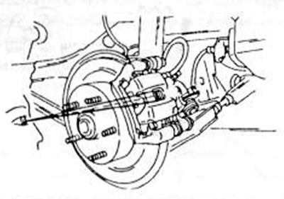
Figure 233. The thickness of the rear wheel brake pad can be seen in the window of the disc brake caliper.
Brake pads are also replaced if the difference between the thicknesses of the brake pad linings is more than 2.0 mm.
17.4.2. Removing and installing brake pads
- Raise the rear of the vehicle and place it on jack stands.
- Unscrew the rear ears.
- Release the handbrake.
- Using the drawing 234, unscrew the handbrake cable from the cable mount and from the control lever. To do this, you need to use two wrenches to loosen the mounting nuts and then remove the cable from the lever.
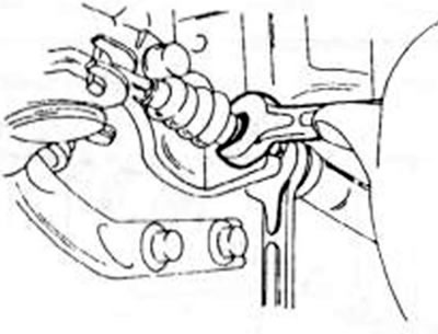
Figure 234. Releasing the handbrake cable from the rear brake caliper
- Remove the upper brake cylinder mounting bolt and fold the caliper down. Both V-shaped springs can be removed immediately.
- Remove the brake pads and lining plates from the brake caliper mounting frame.
Clean the free parts of the disc brake caliper thoroughly and check that the sliding surface of the brake pads does not have any rusty areas (if necessary, clean with a wire brush). Before installing new brake pads, slightly open the air bleed screw and unscrew the piston as shown in the figure 235 with a special tool. If there is no tool, you can help in other ways if necessary.
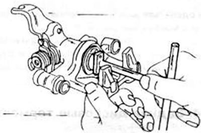
Figure 235. Unscrewing the piston from the rear brake caliper. A special tool must be used for this.
The air bleed hose must be placed on the bolt to collect the leaking fluid.
When installing, proceed as follows:
- Insert both brake pads into the guides. Make sure the brake pads are in the correct position when reinstalling the same pads. Install the lining plates in accordance with assembly drawing 236. The plates are included in the repair kit and must be used. Lubricate the plates with the supplied grease to adhere them to the brake pads.
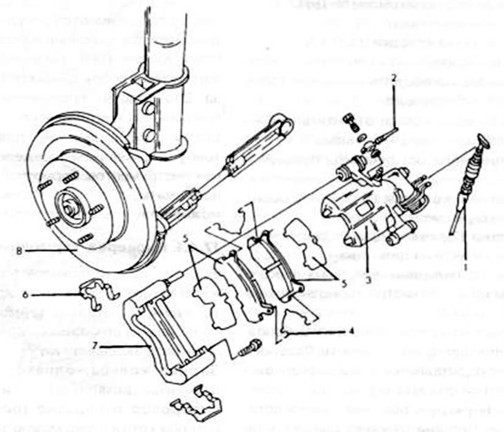
Figure 236. Details of the rear brake pad of the disc brake mechanism. 1. Handbrake cable; 2. Brake hose; 3. Disc brake caliper cylinder; 4. V-shaped spring; 5. Brake shoe and lining plate; 6. Guide springs; 7. Caliper mounting frame; 8. Brake disc
- Insert V-springs.
- Insert the disc brake caliper cylinder through the brake pads, being careful not to damage the rubber seals, until the top bolts can be re-inserted.
- Tighten the bolts to a tightening torque of 16–24 Nm.
- Hang the end of the handbrake cable on the lever, and as shown in the figure 234, tighten both nuts to a torque of 20-24 Nm. There should be no gap between the handbrake cable and the control lever.
- Place the car on the wheels and tighten the nuts to 90-120 Nm. Once the car is on the floor, press the brake pedal several times to engage the brake pads.
Think about the fact that new brake pads are initially only "slowed down" and do not have a full load.
Caution: Never remove brake dust with compressed air. Use only a damp cloth to remove dirt. After this, throw away the rag - asbestos dust.
17.4.3. Removing and installing the disc brake caliper
The brake caliper can be removed without unscrewing the mounting frame from the shock absorber strut.
- Place the rear of the car on jack stands and unscrew the rear wheels.
- Loosen the hollow bolt of the brake hose on the brake caliper and remove the hose. Place a container underneath to collect the leaking liquid. Do not lose the sealing washers.
- Remove the brake pads as described in the last chapter and remove the caliper completely. To do this, you simply need to pull the cylinder off the lower support bolt. If the mounting frame needs to be removed, both bolts - one at the top and one at the bottom - are released. The installation of the disc brake caliper cylinder and mounting frame is carried out in the reverse order of removal, as already described when installing the brake pads. If the mounting frame was removed, tighten the bolts to 45-67 Nm. Screw on the brake hose with new O-rings and tighten to 25 Nm. Finally, bleed the brake system.
17.4.4. Repair of the disc brake caliper
Figure 237 shows the assembly drawing of the brake caliper, however, it should be noted that the tool shown in the figure is used to unscrew the piston 236 tool.
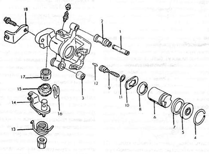
Figure 237. Assembly drawing of the lower caliper of the disc brake mechanism. 1. Guide bolt 2. Sleeve; 3. Rubber bushing; 4. Safety ring; 5. Dust ring; 6. Piston; 7. Piston seal ring; 8. Snap ring; 9. Adjusting spindle; 10. Thrust washer; 11. "O"-shaped sealing ring; 12. Connecting ring; 13. Return spring; 14. Control lever; 15. Rubber cuff; 16. Safety rod, cuff; 17. Needle roller bearing; 18. Brake cable mounting bracket
The following text describes a complete repair of the brake caliper. Work not included in the scope of work may be considered.
- Thoroughly clean the outside of the cylinder and clamp the cylinder in a vice.
- Remove the guide bolt (1) and rubber seal (2) from the hole.
- On the other side of the brake caliper, push out the rubber bushing (2).
- Remove the safety ring (4) from the inner part of the brake caliper bore.
- Remove the dust ring (5) and unscrew the piston (6) using the special tool shown in Figure 235. Otherwise, you need to place a similar device on the piston groove and remove the piston. The piston is screwed onto the adjusting spindle.
- Remove the snap ring (8) from the hole.
- Grasp the adjusting spindle (9) with your hand and remove the thrust washer (10) and "O" sealing ring (11). The connecting pin (12) can be removed or left in the brake caliper.
- The remaining parts may not need to be removed as a puller is required to remove the needle roller bearing (17). If you need to break the control arm (14), it might be better to replace the bearing at a Mazda workshop or install a new brake caliper.
- If grooves, rust spots or other damage are found on the inside of the bore, the entire cylinder must be replaced. Minor irregularities can be smoothed out with fine sandpaper. The cylinder seal ring and dust ring must be replaced. The rubber bushing (3) and the rubber dust cap (2) in the cylinder can be replaced if necessary; the same applies to the guide bolt (1).
- When assembling, lubricate all internal parts with brake fluid or brake grease and then assemble the brake caliper cylinder in the following manner:
- Lubricate the new sealing ring (7) with brake fluid or the grease supplied in the repair kit and insert it into the cylinder bore groove. Press your fingers well into the groove. The ring has a square cross-section and is inserted accordingly.
- Insert the connecting pin into the inside of the cylinder like this. so that it fits into the groove of the control lever.
- Place a new "O"-ring on the adjusting spindle and assemble the spindle with the lock washer. Insert the parts directly into the hole. Both spindle pins must fit into the corresponding holes. Secure the parts using the spring retaining ring (8).
- Insert the pistons into the hole and, using a special tool, turn them to the right in the hole. Screw the piston in completely and then direct the cutouts in the piston so that they are installed transversely and vertically in relation to both brake caliper mounting lugs.
- Lubricate the new dust ring with brake fluid and place it on the cylinder.
- Check the caliper again for cleanliness before reinstalling it.
Note: The various components of the disc brake caliper must be lubricated with the grease supplied in the repair kit. The cylinder sealing ring is lubricated with red grease, the "O" sealing ring with white grease, and the remaining parts with orange grease.
17.4.5. Brake discs
The brake discs are removed in accordance with the instructions in the chapter on replacing wheel bearings, i.e. they can be removed down to the hub after the caliper cylinder is unscrewed at the top and pressed at the bottom. Brake discs can be checked as follows:
- Check the surfaces of the discs for rust deposits. Light rust stains can be removed with fine sandpaper.
- Measure the brake disc thickness to ensure no difference in thickness exceeds 0.7 mm. Use a micrometer, as shown in Figure 224, or a caliper for these measurements. The minimum disc thickness is 8.0 mm. If a disc is found to be warped, it can be reinstalled on the hub and secured with two wheel nuts.
- Install the dial indicator on the steering knuckle as shown in figure 225 for the front disc, and position the tip of the needle against the outer edge of the brake disc. Slowly rotate the disk and read the dial indicator. If they are greater than 0.10 mm, it can be assumed that the disc is warped or a foreign object has gotten between the disc's supporting surface and the hub.