


17.3.1. Replacing brake pads
The thickness of the brake linings can be checked through the inspection hole in the brake caliper plate. To do this, you need to shine a flashlight into the hole.
The thickness of the brake pad material must not be less than 1.0 mm. Otherwise, replace the brake pads as follows, using Figure 226:
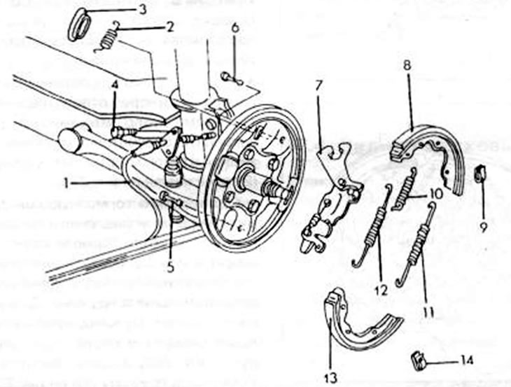
Figure 226. Rear wheel brake parts. 1. Handbrake cable; 2. Return spring; 3. Plug; 4. Mounting bolt. Brake cable; 5. Anchor pin. Brake pads; 6. Anchor pin. Brake pads; 7. Push bar with regulator; 8. Press-on brake shoe; 9. Spring clamp. Anchor pin; 10. Return spring; 11. Lower return spring of the shoe; 12. Upper return spring; 13. Pressed brake shoe; 14. Spring clamp. Anchor pin
- Place the rear of the car on jack stands.
- The front wheels should be supported in a suitable manner (for example, put bricks under), to prevent the car from rolling off the trestles.
- Remove the rear wheels.
- Release the handbrake.
- Remove the brake drum as described in the relevant chapter. In some cases, it can be difficult to simply pull the drum out.
- In this case, using Figure 227, you need to place a screwdriver on the control lever from the rear side of the brake caliper plate and press the lever outward and then upward. This disengages the adjustment mechanism and increases the distance between the brake linings and the drum brake.
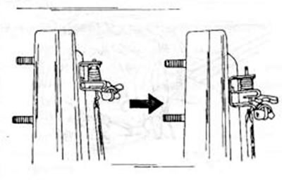
Figure 227. Releasing the brake shoes from the rear side of the anchor plate.
- On each brake shoe, grasp the head of the anchor pin (6) with pliers and turn it 90° until the spring clip (9) can be released from contact with the pin.
- Remove the return spring (2) from the rear side of the brake caliper plate from the handbrake control lever.
- Release the handbrake cable from the brake caliper plate while removing the mounting bolts.
- Using pliers or a screwdriver, remove the brake pads (8) and (13) from the pistons without damaging the wheel brake cylinder seals. The upper return spring (7) is then released and can be removed.
- Remove the lower part of the brake pad from the lower support and the pad from the brake caliper plate. In this case, the lower return spring (11) is released and can be removed from the shoe. Remove the brake pressure rod (7) with the regulator and the handbrake cable from the rocker arm.
- If the pads are reinstalled, they must be marked according to which side they were on.
- If grooves appear on the surface of the brake drum, the drum can be turned out, provided that the specified maximum diameter is observed. It ranges from 201.5 mm or 230.1 mm, depending on which drum size is used. Also measure the brake drum for radial runout, especially if the brakes have overheated during operation. The difference in diameter should not be more than 0.10 mm at any point. If the brake pad material thickness is less than 1.0 mm, the entire set of pads must be replaced.
- Bent springs, even if they were bent when removed, must be replaced. The wheel brake cylinder is described in Chapter 17.3.2.
- Installation of brake pads is carried out in reverse order, observing the following points:
- Apply a small amount of heated bearing grease to the brake caliper plate where the pads rub, and also lightly lubricate the lower brake stop and the guide surfaces of the wheel brake cylinder.
- Insert the handbrake control lever from the outside through the hole in the brake caliper plate (figure 228) and secure the return spring and lever to the rear of the caliper plate. This is the spring (2) shown in Figure 226.
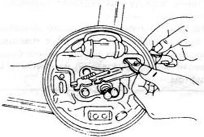
Figure 228. Installing the push rod and brake shoe control lever and rocker arm through the brake caliper plate.
- Place the released brake shoe (8) on the control lever and then install it in the wheel brake cylinder and opposite the support plate of the brake mechanism caliper. Secure the pads using an anchor pin and a spring clamp. To do this, you need to compress the spring clamp until the head of the pin fits through, and then turn the clamp 90° to protect the pin. Install the spring (10) as shown in Figure 226.
- Insert the lower return spring (11) into the installed shoe and the other end of the spring into the pressure brake shoe (13). Insert the shoes into the support on the bottom side. To do this, you need to grab the pads as shown in Figure 229 and pull outward until the spring protrudes far enough for the pads to enter the support. Bring the pads on the upper side into contact with the control lever and brake cylinder and secure them with the anchor pin and spring clamp.
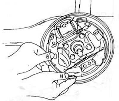
Figure 229. Pull the shoe outward until it can be inserted at the top and bottom.
- Insert the upper return spring into the block and stretch the spring with pliers as shown in Fig. 270 until the hook can be inserted into the other block.
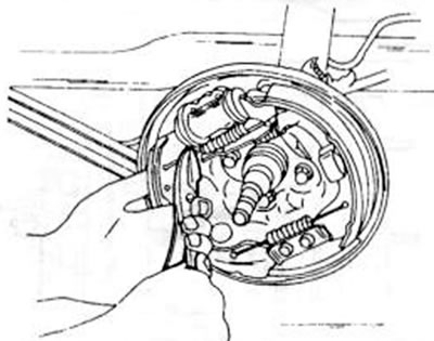
Figure 230. Installing the upper brake shoe spring
Based on website data: MAZBOOK
- To make it easier to install the brake drum, you need to move the pads as far inward as possible. To do this, insert a screwdriver into the toothed segment, as shown in Figure 231, and move the segment in the direction of the arrow.
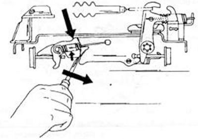
Figure 231. Bring the installation mechanism to its original position while moving the toothed segment in the direction of the arrow using a screwdriver
- Install the drum brake as described in the relevant chapter. New nuts must be used all the time, and after tightening them to 100–180 Nm, they must be counter-tightened with a blunt chisel.
- After installing the brake pads and brake drums, it is necessary to bleed the air from the brake system if the brake cylinder is removed.
17.3.2. Ear brake cylinder
Wheel brake cylinders do not necessarily need to be removed to be repaired. However, in this case, you need to ensure impeccable cleanliness. When repairing the wheel brake cylinder, the following points must be observed:
- Replace all rubber seals. There are repair kits for this purpose and all parts included in the kit must be used during assembly.
- Disassembly and assembly must be carried out in the cleanest conditions.
- All rubber seals should be soaked briefly in clean brake fluid before installation.
- When ordering a repair kit, please provide the chassis and model number, as the wheel brake cylinder is sometimes replaced without prior inspection. To remove the wheel brake cylinder:
- Remove the brake pads (chapter 17.3.1).
- On the rear side of the brake caliper plate, loosen the brake line union nut.
- Unscrew the wheel brake cylinder from the brake caliper plate.
- Disassemble the cylinder using Figure 232:
- Remove the dust cap (1) on both sides.
- Both pistons (2), as well as other internal parts, are pushed out of the cylinder.
- Remove the cuffs (3) from the piston using your fingers. Clean all parts with clean brake fluid or alcohol.
- If grooves appear on the cylinder bore, the entire cylinder must be replaced. Disassembly and assembly are carried out in the reverse order of the work described.
- Place the spring in both spacers and insert the parts. The flat sides of the cuffs must be put on on both sides in accordance with the installation drawing.
- Make sure that the edges of the cuffs do not curl when inserting the piston. Lubricate the cuffs and inner parts of the dust cap with rubber lubricant.
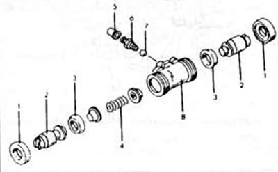
Figure 232. Assembly drawing of the wheel brake cylinder. 1. Dust cap; 2. Piston; 3 Piston cuff; 4. Spring; 5. Rubber protective cap; 6. Air bleed screw; 7. Steel ball; 8. Wheel brake cylinder bushing