


Contents: 17.2.1. Brake pad inspection ⇓ 17.2.2. Removing and installing…⇓ 17.2.3. Removing and installing the…⇓ 17.2.4. Repair of the brake caliper ⇓ 17.2.5. Brake discs ⇓
Disc brakes use sliding calipers with two self-adjusting brake pads, one on each side of the brake disc.
A separate piston acts directly on the brake pad and the reactive force from this pad pulls the other brake pad towards the brake disc.
17.2.1. Brake pad inspection
If you hear noise when you apply the foot brake, you need to check the brake pads. The thickness of the brake pad can be checked without removing the pads. However, the front wheels need to be unscrewed, the caliper cylinder has an inspection hole (figure 215), although it's difficult to measure the thickness of the brake pad linings, it can still determine whether they have worn down to 2.0 mm. The groove on the friction surface of the lining should still be clearly visible. Brake pad thickness is never checked on just one side, as it may happen that the brake pads on the other side may have different wear.
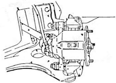
Figure 215. The thickness of the brake pad linings can be checked through the inspection hole in each brake caliper
Brake pads must be replaced if the difference between the lining thicknesses is more than 2.0 mm.
17.2.2. Removing and installing brake pads
When replacing brake pads, always inspect one side at a time to ensure that the piston on the other side is not pushed out when the piston of the brake seat being inspected is pressed into the hole.
- Place the front of the car on jack stands.
- Unscrew the front wheels.
- Using Figure 216, loosen both indicated bolts and remove the valve seat. Leave the saddle on the hose, but secure it with a piece of wire or rope, as shown in Figure 217, so that it does not dangle.
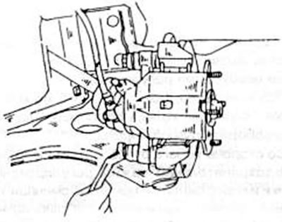
Figure 216. Removing or installing the brake caliper cylinder.
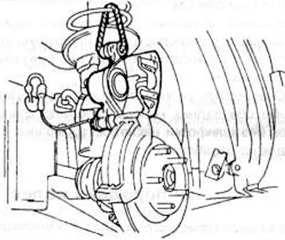
Figure 217. After releasing the lower pin, secure the brake caliper in the indicated position. The caliper rotates freely on the top pin.
[The primary source is the website: MAZbook.ru]
- The brake pads are now free and can be removed along with the inserts and V-spring. Ensure the precise placement of parts.
Clean the free parts of the brake caliper thoroughly and check that the sliding surfaces of the brake pads are free of rust (if necessary, clean with a wire brush). Before installing new brake pads, slightly open the vent plug and press the piston into the hole.
The ventilation hose must be placed on the plug to collect the spilled liquid. You can also push the plunger in while the plug is opening. This way you can prevent air from entering the brake caliper.
When installing, proceed as follows:
- Insert both brake pads into the guides. Make sure that the brake pads are in the correct position if the old pads are being reinstalled. Install the inserts in accordance with the installation drawing in Figure 218. The insert washers are included in the repair kit and must be used. The grease supplied with the kit must be applied to the washers so that they adhere to the brake pad.
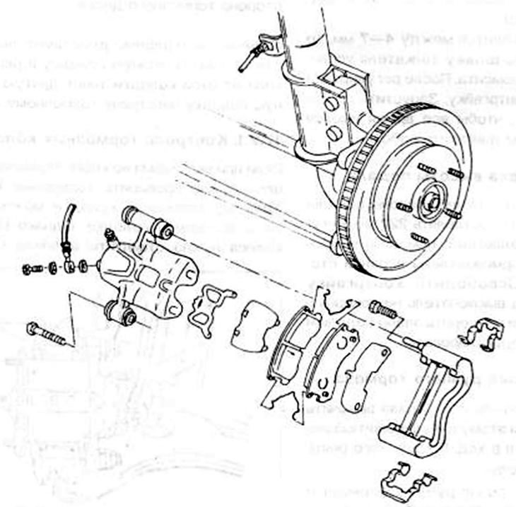
Figure 218. Individual parts of the brake shoe
- Insert the V-spring (not installed in all brakes).
- Install the brake valve cylinder through the brake shoe, being careful not to damage the rubber seal, until the lower bolt can be reinserted.
- Tighten the bolt to a torque of 31–41 Nm
- Lower the vehicle onto its wheels and tighten the wheel nuts to 90–120 Nm.
After the car has been parked on the ground, press the brake pedal several times to seat the brake pads on the brake calipers. It is important to remember that new brake pads should only "slow down" and should not initially have a full braking load.
17.2.3. Removing and installing the brake caliper
The brake caliper can be removed without unscrewing it from the shock absorber strut mounting frame.
- Place the front of the car on jack stands and unscrew the front wheels.
- Loosen the hollow plug on the brake hose on the valve seat and remove the hose. Place a container underneath to collect the leaking liquid. But lose the sealing washers.
- Remove the brake pads as described in the last chapter and remove the brakes completely. To do this, you simply need to pull the cylinder off the top support bolt.
If you need to remove the mounting frame, then both bolts, one at the top and one at the bottom, must be loosened.
The installation of the brake caliper cylinder is carried out in the reverse order of removal, as already described when installing the brake pads. If the mounting frame was removed, tighten the bolts to 80-100 Nm. Screw on the brake hose with a new seal and tighten to 25 Nm. Finally, bleed the brake system.
Caution: Never remove dust from brakes with compressed air. Use only a damp cloth to remove dirt. After this, the rag should be thrown away due to the presence of asbestos dust.
17.2.4. Repair of the brake caliper
Using Figure 219:
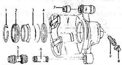
Figure 219. Brake caliper disassembly details. 1. Safety ring; 2. Dust sealing ring; 3. Brake piston; 4. Cylinder sealing ring; 5. Guide bolt; 6. Rubber cuff, bottom; 7. Bushing, top; 8. Rubber dust cap; 9. Air bleed screw
- Thoroughly clean the outside of the cylinder and clamp the brake caliper cylinder in a vice.
- Insert a small screwdriver under the edge of the fastening ring (1) and remove it.
- Also remove the dust seal protective ring (2) using a screwdriver. Perform both of these operations carefully to avoid damaging the brake caliper.
- Insert a piece of wood into the hole in the brake caliper and attach the compressed air line to the connection hole in the brake caliper. In this way, the piston is pressed out and knocked out on the block. Keep your fingers off this item to avoid injury.
- Remove the piston sealing ring (4) from the cylinder groove using the tip of a tool, without scratching the cylinder walls. If scratches, rust stains or other damage are found on the inside of the bore, the entire cylinder must be replaced. Light roughness may be smoothed out with fine sandpaper. The piston sliding surfaces must not be treated with sandpaper.
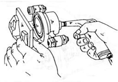
Figure 220. Squeezing the piston out of the valve seat cylinder
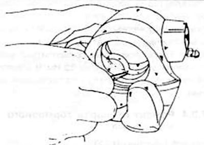
Figure 221. Using a sharp object, carefully remove the sealing ring from the cylinder bore.
The cylinder seal ring and dust seal must be replaced. The rubber bushing (7) and the rubber dust cap in the cylinder can be replaced if necessary; the same applies to the sliding bushings (5).
When assembling, all internal parts must be lubricated with brake fluid or brake grease and then the brake cylinder must be assembled as follows:
- Lubricate the new sealing ring (4) with brake fluid or the grease supplied in the repair kit and insert it into the groove of the cylinder bore. Press it well into the groove with your finger. The ring has a square cross-section and is inserted accordingly. Press the piston into the hole. The open part of the piston faces outward.
- Press the piston with your thumbs as shown in Figure 222. Be sure to ensure that the piston is inserted without tilting. Under no circumstances should the piston be inserted into the hole using mechanical devices.
- Lubricate the new dust ring (2) with brake fluid or brake grease and place it on the cylinder.
- Lubricate the parts shown in Figure 223 with the grease supplied in the repair kit. Lubricate the cylinder mounting bushings with rubber grease and insert the parts shown in the figure into the cylinder.
- Check the brake caliper again for cleanliness before installing it.
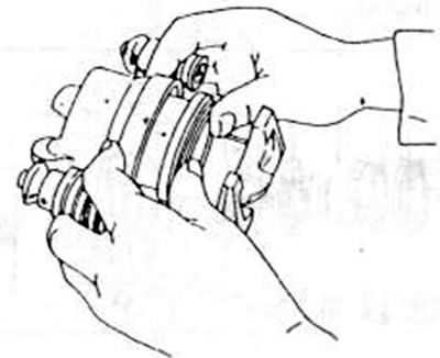
Figure 222. When assembling the brake caliper cylinder, press the piston with your thumbs as shown.
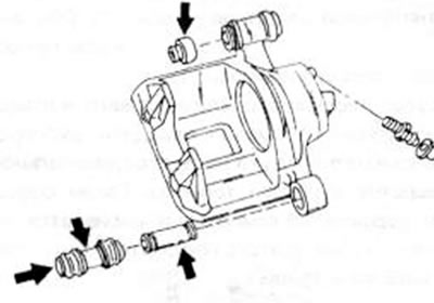
Figure 223. Before assembly, lubricate the areas indicated by the arrows with the grease included in the repair kit
17.2.5. Brake discs
The brake discs are removed in accordance with the instructions in Chapter 14.1.2 when replacing the wheel bearings, i.e. they can be removed in front of the hub after the brake caliper cylinder has been unscrewed at the bottom and pressed upwards.
Brake discs can be checked in the following way:
- Check the surfaces of the discs for rust spots. Small stains can be removed with fine sandpaper.
- Measure the thickness of the brake discs to ensure there is no difference greater than 0.07 mm anywhere. Use a micrometer, as shown in Figure 224, or a caliper for this measurement. The minimum thickness depends on the size of the installed rim. For a 13-inch rim diameter, the minimum thickness is 18.0 mm; for a 14- or 15-inch diameter, the thickness cannot be less than 22.0 mm. If it is determined that the disc is not deformed, it can be reinstalled on the hub and secured with two wheel nuts.
- Install a dial indicator on the steering knuckle as shown in Figure 225 and position the end of the needle against the outer edge of the brake disc. Slowly rotate the brake disc and read the dial indicator. If they are more than 0.10 mm, it can be assumed that the disc is deformed or there is a foreign inclusion between the surface of the disc lining and the hub.
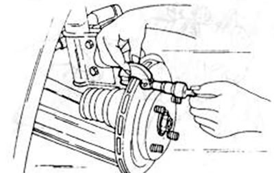
Figure 224. Mark the thickness of the brake discs in the indicated place.
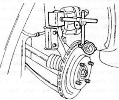
Figure 225. Measuring brake discs according to the indications in the figure using the runout method