


With four-wheel steering installed, the anti-roll bar is removed and installed in a different way, since a special adjustment lever is installed between the anti-roll bar and the rocker arm on the inside of the rear wheel, which is attached to the anti-roll bar using a ball joint. When removing, proceed as follows, using Figure 205. The car must be placed on jack stands at the rear.
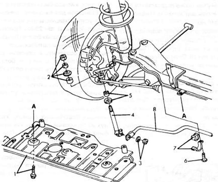
Figure 205. Anti-roll bar components with four-wheel steering installed. 1. Casing; 2. Nuts and fasteners, 12-18 Nm; 3. Nut, 38-47 Nm; 4. Adjustment lever; 5. Bushing and metal disc; 6. Bolt, 43-55 Nm; 7. Sleeve and mounting clamp; 8. Anti-roll bar
Unscrew the rear wheel control protective cover and remove it.
Remove both nuts (2) from the upper end of the adjusting lever and remove the metal disk and the rubber bushing.
Unscrew the nut and disk (3) from the end of the anti-roll bar and push the ball-head bolt out of the lever.
Pull the adjusting lever (4) out of the rocker arm on the upper side. Remove the bushing and metal disk (5) from the lever.
Loosen the bolts and both mounting clamps and remove the clamps. The stabilizer can now be removed.
Check the details in the usual way. The ball joint of the adjusting lever can be knocked out. In this case, replace the entire lever system. When installing, proceed as follows:
- Place the rubber bushings on the rod in the same manner as shown in figure 193, with the difference that the flat side of the sleeve is located at the top.
- Place both mounting clamps on and tighten by hand.
- Insert both adjusting levers into the mounting parts from below and tighten the first nut on the upper end until the end of the thread protrudes by 13.0 mm. This dimension, similar to that shown in figure 194, check with a measuring ruler. In this arrangement of nuts, the second nut must be locked so that the other one cannot turn. The tightening torque is 12-18 Nm.
- Lower the vehicle to the ground and tighten the bolts of both mounting clamps to 43–54 Nm.