


Contents: 15.3.1. Removal ⇓ 15.3.2. Installation ⇓
15.3.1. Removal
In normal two-wheel control, the setup shown in the figure is 203 lower wheel suspension. As you can see in the picture, one of the suspension arms can be adjusted in length to adjust the toe-in. If this wishbone is removed, do not loosen the lock nut in the middle unless the wheels are aligned.
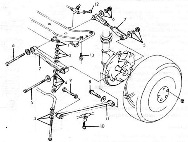
Figure 203. Individual parts of the rear wheel suspension for two-wheel steering. 1. Nuts, 16-23 Nm; 2. Bushings and metal discs; 3. Bolt, metal disk, bushing; 4. Rubber bushings, metal discs, sleeves; 5. Bolts and nuts, 86-120 Nm; 6. Bolts and nuts, 86-120 Nm; 7. Suspension control arm rod; 8. Bolt, 86-120 Nm; 9. Bolt, 64-95 Nm; 10. Bolts; 11. Trailing arm rod; 12. Bolt, 18-27 Nm; 13. Suspension control arm bolts, 37-55 Nm
- Place the rear of the car on jack stands. Engage first gear or reverse to prevent the vehicle from rolling off the jackstand.
- Unscrew the rear wheels.
- Loosen both nuts (1) on the upper side of the anti-roll bar arm. remove the washers and rubber bushings (2), remove the bolt (3) and remove the individual parts (4) in the middle. These works are carried out on both sides.
- Release the rear crossmember mount and lower the crossmember on the jack to gain access to the individual fasteners.
- Release the bolts and nuts (5) and (6) of the transverse suspension arm on the outer side from the shock absorber strut and disconnect the connection. On the inside of the wishbone, remove the bolts and nuts securing it to the body and remove both wishbones.
- Unscrew the bolts (8) and (9) of the trailing arm rod from the shock absorber strut and then release them from the body. Loosen the bolts (10) and remove the trailing arm rod.
15.3.2. Installation
The bushings in the wishbones and the trailing arm rod cannot be replaced. If they need to be knocked out, then the corresponding independent wheel suspension arm must be replaced.
The installation of the longitudinal arm is carried out in the reverse order of removal, however, some points must be observed:
- Install the suspension wishbone from the inside, insert the bolts and put on the nuts. Tighten the nuts only by hand, since the final tightening is carried out when the car's wheels are on the ground, i.e. the wheel suspension is loaded.
- Install the wishbone rod and tighten the bolts by hand. These bolts should also be tightened with the vehicle loaded, but only after the rear wheel alignment has been checked (see chapter 15.8).
- Install the anti-roll bar in accordance with chapter 15.4.
- Place the car on its wheels and rock the rear end several times.
- Place the wishbone on the supports. Tighten all bolts and nuts to a torque of 86-120 Nm.
- Put on the longitudinal lever. The bolts on the body side are tightened to 64-93 Nm, the bolts on the wheel hub support side are tightened to 88-120 Nm.
- The geometry of the rear wheels needs to be checked and adjusted in the box (see chapter 15.8).