


Contents: Air conditioning system ⇓ Examination ⇓ Topping up the system with…⇓ Heating system ⇓ Odors from the air conditioner ⇓
Air conditioning system
1. To ensure that the air conditioning system is fully operational, the following checks should generally be performed:
- a) Inspect and check the condition of the compressor drive belt. If it is worn out or shows signs of decay. replace it.
- b) Check and, if necessary, adjust the belt tension (see chapter V.
- c) Inspect the system hoses for cracks, swelling, hardening and decomposition of rubber. Pay attention to possible traces of oil on the hoses and their connections. If you have the slightest suspicion that the hose is faulty, replace it.
- d) Inspect the condenser core for any debris or insects. If necessary, blow out the core with compressed air.
- d) Make sure the system is fully charged with refrigerant.
2. At least once a month, turn on the system and let it run for at least 10 minutes, including in winter.
3. Serious repairs to the air conditioning system require specialized equipment and experience. For this reason, such work is usually beyond the capabilities of a car enthusiast, but is not considered here. However, some simple maintenance procedures and replacement of some system parts may well be within his capabilities and can be performed without special equipment and special skills.
4. The most common reason for inefficient air conditioning is a refrigerant leak. If you notice a decrease in the system's cooling capacity during operation, the following quick checks will help you determine if the cause is a low refrigerant level.
Examination
5. Warm up the engine to normal operating temperature.
6. Set the air temperature control to the coldest position and turn the fan to the highest speed. Open the doors to prevent recirculation of cooled air.
7. After the system has reached a steady temperature, feel the two tubes connected to the evaporator on the engine bulkhead.
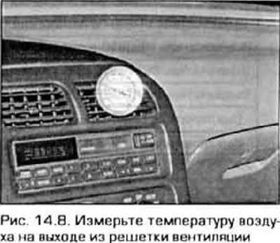
8. One of them. the smaller diameter tube connecting the condenser to the evaporator should be cold, and the second, thicker tube coming out of the evaporator and going to the compressor should be slightly cool (+12...+16°C). If the evaporator outlet tube is significantly warmer than the inlet tube, the system needs refilling. Measure the temperature of the air coming out of the central ventilation grille (figure 14.8) - It should be 20-25 degrees lower than the outside air temperature, down to approximately +5°C. If the air doesn't cool significantly, the system most likely requires refilling. Further testing of the air conditioning system is beyond the capabilities of the car owner and should be entrusted to specialists.
Topping up the system with refrigerant
Please note: Until 1993, air conditioning systems were filled with R-12 refrigerant. Beginning in 1994, this refrigerant was replaced by the more environmentally friendly R-134a. These refrigerants are not compatible, nor are the oils used in air conditioning systems. The systems have different pipe connections, so it is impossible to install a part from a new system into an old one and vice versa. When recharging the system or replacing refrigerant, make sure the correct type of refrigerant is used.
Note: Models filled with R-12 refrigerant should only be serviced at specialized stations.
Models produced since 1994 (with R-134a refrigerant)
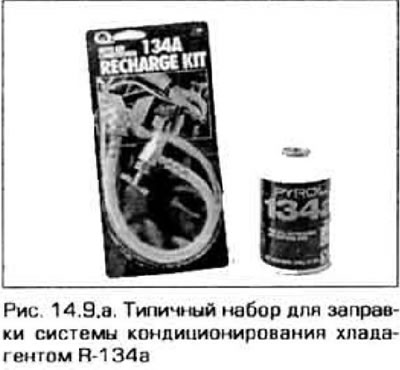
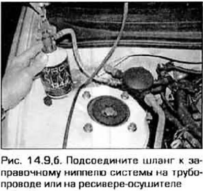
9. Purchase a refill kit (figure 14.9,a). The kit includes a 400-gram can of R-134a refrigerant, a tap, and a piece of hose that connects between the tap and the valve on the low-pressure side of the system. Low pressure valve of the system (filling valve) located in the pipeline leading to the engine bulkhead (figure 14.9.6). Since one can of refrigerant may not be enough to completely refill the system, it is better to purchase an extra can just in case.
 |
 |
Caution: Never add more than two cans of refrigerant to the air conditioning system - this is the capacity of the entire system.
10. Connect the supplied charger to the system, strictly following the manufacturer's instructions. Turn the charger valve knob to raise the needle and screw the charger onto the refrigerant can (check that the sealing ring inside the charger adapter is in place).
Caution: When working with refrigerant under pressure, wear a protective face shield.
11. Remove the protective cap from the system filling valve and connect the filling kit hose connector to it.
Caution! DO NOT connect the fill hose to the high-pressure side of the system! The hose connector included is designed for connection to the low-pressure side only.
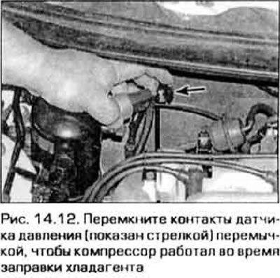
12. Warm up the engine to normal operating temperature and turn on the air conditioner. Make sure the charger hose does not come into contact with rotating parts of the engine. If the air conditioning system is significantly discharged, the pressure sensor on the receiver/dryer may not turn on the compressor, so disconnect the sensor connector and short the two connector terminals with a jumper wire (figure 14.12).
13. Turn the charger valve until the valve needle pierces the refrigerant can, then turn the valve back to open the passage for the refrigerant. You should hear the noise of gas entering the system. Fill the system until both evaporator tubes - the inlet and outlet - feel approximately the same temperature. Add refrigerant in portions and allow time between charges for stabilization.
Note: During the charging process, the refrigerant can will cool down and may freeze so much that the supply of refrigerant to the system will stop. To prevent this from happening, wrap the jar in a towel soaked in hot water.
14. You can use a thermometer to measure the temperature of the air coming out of the ventilation grille into the passenger compartment (see Figure 14.8). If the system is charged and working properly, the temperature should drop to approximately 5°C.
15. After emptying the can, turn the valve of the filling tap to the closed position and disconnect the hose from the low pressure valve of the system. Place the protective cap on the valve.
16. Unscrew the filling device from the can and save it until the next time you fill it up.
Heating system
17. If the air coming out of the ventilation grilles is not heated enough, this may be the result of the following malfunctions.
- a) The thermostat is stuck open and the engine coolant cannot get hot enough to warm up the heater core. Replace Thermostat (paragraph 3).
- b) The heater hose is clogged and does not allow the necessary fluid circulation in the heater radiator. Feel both heater hoses on the engine bulkhead - they should be hot. If one of the hoses remains cold, either the hose or the heater core is clogged, or the heater control valve is closed. Disconnect the hoses from the heater radiator and flush the radiator with clean water from a hose. If the radiator is not clogged and there is no fluid circulation, remove both heater hoses and flush them with water
- c) If the heater radiator is clogged and flushing does not remove the blockage, replace it.
18. If the heater fan speed does not match the switch setting, the cause may be a faulty fuse, power supply circuit, motor relay, speed switch, or resistor (see paragraph 10).
19. If air does not come out of the grilles, then:
- a) Turn on the ignition and turn on the fan. Put your ear to the ventilation grill and listen if the fan is working.
- b) If the fan does not work, although the speed switch and resistor are working properly, then the fan motor may be faulty (see paragraphs 10 and 11).
20. If the carpet under the heater radiator has become damp, or steam is coming through the grilles, this may indicate a leak in the heater radiator. Take it off (see paragraph 13) and replace with a new one (heating radiators are generally not repaired).
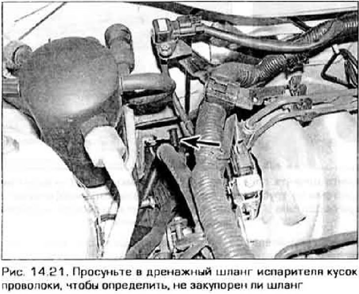
21. Check the drain hose from the heater/evaporator unit on the right side of the engine bulkhead and make sure it is connected. that it is not corked (figure 14.21). If wet steam is coming out of the system's air ducts, the hose may be clogged with leaves or road dirt.
Odors from the air conditioner
22. The unpleasant smell that appears in the cabin when the air conditioner is running is caused by mold growing on the evaporator core. The warm, humid environment in this area provides a favorable habitat for them.
23. On most models, the evaporator is difficult to reach. Some workshops that have addressed this issue employ labor-intensive and expensive techniques that involve opening the evaporator housing, cleaning, and treating the core with strong disinfectants. It is possible to carry out such disinfection in a garage, but it will require chemical reagents stronger than ordinary deodorants or pest control agents.
24. Auto supply stores may have aerosol cans for this job, but be aware that effective products are usually expensive. If you managed to obtain such an aerosol, then proceed as follows. Turn on the air conditioning system, turn on the fan at the highest speed and let the system run in RECIRC mode (recirculation) for approximately 10 minutes. Dry the system components by setting the air temperature to maximum. Then turn off the compressor by disconnecting its electrical connector (see paragraph 16).
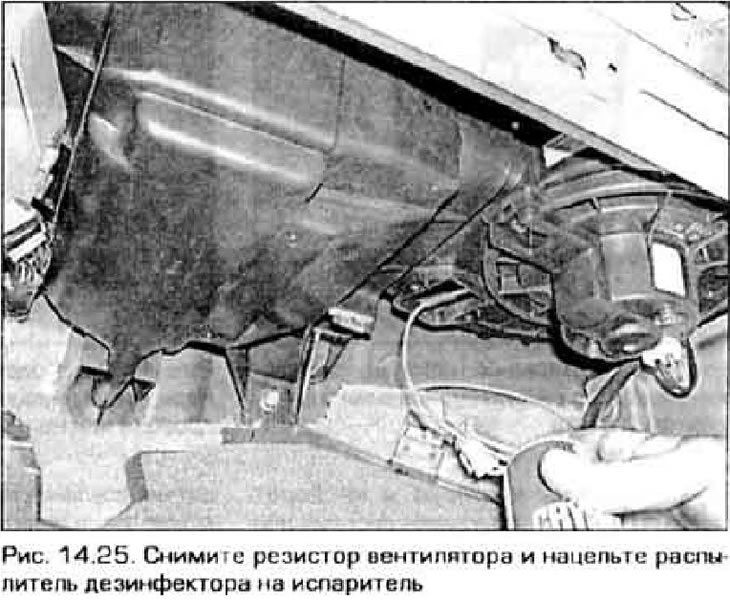
25. Usually the can is supplied with a long hose with a sprayer. Remove the otolith fan resistor (see paragraph 10), aim the sprayer at the left side of the hole, in the area of the evaporator grille (figure 14.25) and treat the evaporator according to the manufacturer's instructions. Try to cover the entire surface by directing the spray downwards, upwards, leftwards, and rightwards. Follow the manufacturer's recommendations regarding spraying duration and intervals between reapplications.
26. After treating the evaporator, to prevent mold from reappearing, keep the evaporator drain hose clean (see figure 14.21). After running the air conditioner for a long time, turn on the defrost (DEF) mode for a short time to dry the evaporator.