


All brakes are self-adjusting. Disc brake pad wear is compensated automatically, while drum brakes have an adjustment mechanism that is activated when the brakes are applied. The adjustment mechanism operates until the drum brake shoe linings are worn to a thickness of 2 mm.
The hydraulic brake system consists of two diagonal circuits. The master cylinder has a separate reservoir for each circuit. In case of failure of one of the circuits, braking is still possible and is carried out by two wheels (one front and one back). A dual control valve redistributes hydraulic pressure to prevent the rear wheels from locking before the front wheels under heavy braking. The warning light on the instrument panel warns of a low brake fluid level in the system. The lamp is switched on by a switch installed in the master cylinder reservoir.
The parking brake has an independent mechanical drive to the rear wheels. The parking brake lever is located between the front seats.
The brake booster, mounted on the heat shield in the engine compartment, uses manifold vacuum and atmospheric pressure to operate.
After completing work on any part of the brake system, perform a test drive (be sure to drive on a clean, dry and level road), to check the operation of the brakes. Test the brakes at various speeds, pressing the pedal hard and then gently. The car should stop smoothly and not pull to one side. Avoid locking the brakes - this reduces braking effectiveness.
The condition of the tires, the vehicle's load, and wheel balance also affect braking.
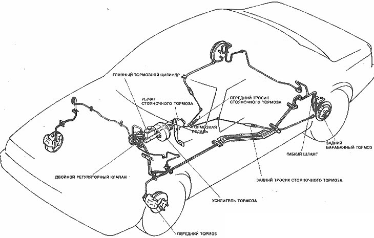
Location of brake system components
Based on website data [mazbook.ru]