


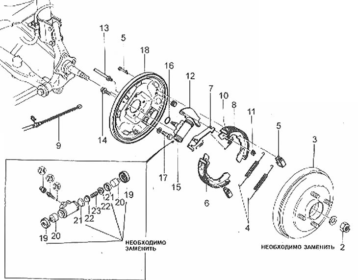
Rear drum brake component locations
2. Hub nut; 3. Brake drum; 4. Return springs; 5. Brake shoe support posts and their springs; 6. Leading brake shoe; 7. Regulator; 8. Slave brake shoe; 9. Parking brake cable; 10. Brake shoe pressure spring; 11. Bracket; 12 Control lever; 13. Brake pipe; 14. Wheel brake cylinder bolt; 15. Working brake cylinder; 16. Gasket; 17. Bolts; 18. Brake support shield; 19. Dust covers; 20. Pistons; 21. Piston seals; 22. Spring supports; 23. Spring; 24. Rubber cap; 25. Bleed nipple; 26. Steel ball
1. When working with brake system components, be aware of asbestos dust generated by wear on brake linings. Do not inhale dust - it is harmful to health.
2. Raise the vehicle and securely support the wheel alignment system on axle stands.
3. Remove the wheel.
Note: All four rear pads must be replaced at the same time. Do not mix up the pads when installing.
4. Remove the drum-hub assembly (Section 1). If the drum cannot be removed, remove the plug from the support plate, insert a screwdriver through the hole and press on the support post spring to widen the gap as shown in the illustration. If the drum still cannot be removed, loosen the parking brake lever adjusting nut.
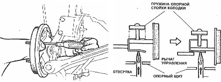
Release the brake shoe support springs by inserting a screwdriver through the hole in the support shield
5. Remove the brake shoe return springs (photo).
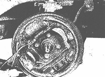
Remove the return springs using pliers
6. Remove the support strut springs and the struts themselves (photo).
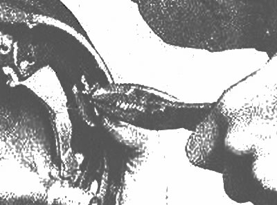
Compress the support strut spring and rotate the strut to release it from the spring |
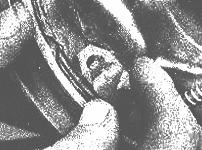
Remove the support strut spring |
7. Remove the leading brake shoe and adjuster. You may need to loosen the adjuster with a screwdriver as shown in the illustration.
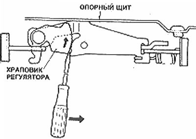
Insert a screwdriver into the adjuster ratchet and move it in the direction shown (arrow) to release the adjuster
8. Remove the driven brake shoe and disconnect the parking brake cable.
9. Remove the bracket and disconnect the control lever from the block (photo).
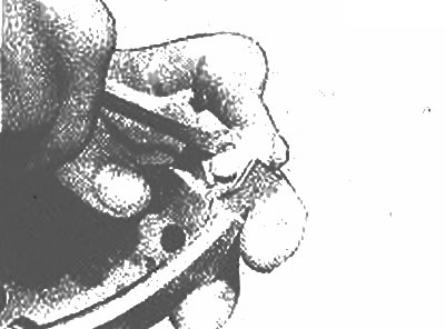
Using a small screwdriver, remove the bracket securing the control arm to the driven brake shoe
10. Lightly grease the surface of the backing plate with white lithium grease at the points shown in the illustration. Avoid contact of lubricant with rubbing surfaces.
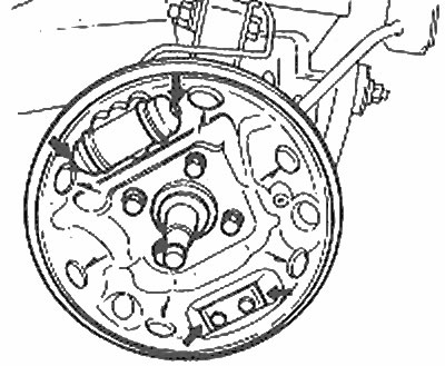
Lubrication points for the support shield and the boots of the working brake cylinder
11. Install the control lever onto the new driven brake shoe.
12. Install the driven brake shoe together with the pressure spring.
13. Connect the parking brake cable.
14. Assemble the leading brake shoe and the adjuster, connect the adjuster assembly into place (photo).
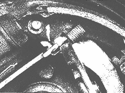
Connect the brake shoe pressure spring to the adjuster using pliers
15. Install the support strut springs.
16. Install the return springs.
17. Center the brake pad assembly (photo).
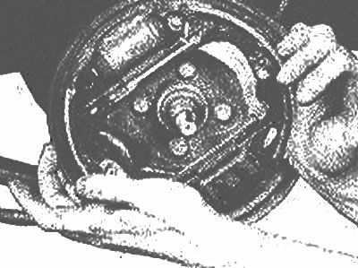
After installing all components, center the brake assembly with clean hands
18. Inspect the brake drum for cracks, scratches, deep grooves and darker or lighter spots. If these spots cannot be removed with fine sandpaper and/or other damage listed above is found, the drum must be re-ground on an appropriate machine (contact a specialist) or replaced (depending on the degree of damage).
Note: The maximum diameter is stamped on each brake drum (photo).
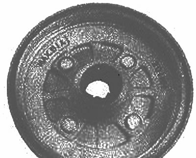
The maximum diameter is marked inside the brake drum
The original article is posted on [mazbook.ru]
19. Install the hub/brake drum assembly and adjust the wheel bearings (Section 1).
20. Install the wheel, insert the wheel nuts and tighten them to the tightening torque specified in the Specifications. Lower the car to the ground.
21. Press the brake pedal several times to adjust the brakes.
22. Check the operation of the parking brake. adjust it if necessary.
23. If new brake pads have been installed, avoid heavy braking during the first few kilometers, when the new pads have not yet fully bedded in.