
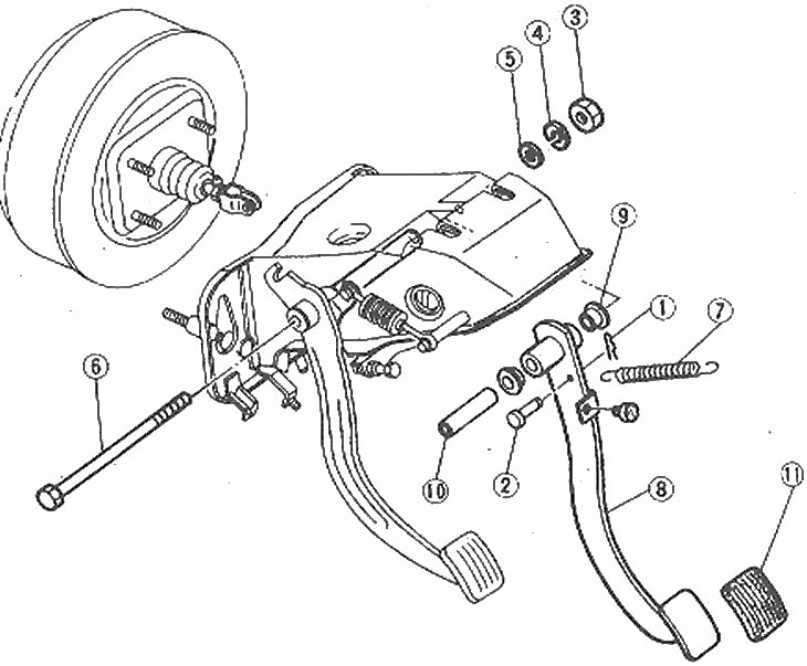
Brake Pedal Assembly Components
1. Hairpin; 2. Pin with hole; under the hairpin; 3. Nut; 4. Spring washer; 5. Flat washer; 6. Bolt; 7. Return spring; 8. Pedal; 9. Bushings; 10. Axis; 11. Pads; 12. Rubber stop
1. Remove air duct and trim from under dashboard to gain access.
2. Remove the pin and remove the pin.
3. Remove the pinch bolt, nut and washers.
4. Disconnect the return spring and remove the pedal.
5. Inspect the assembly. Check if the bushings are worn out, if the pedal is bent or damaged. Inspect the pad for wear damage and the pinch bolt for deformation. Check that the return spring is not damaged or weakened.
6. Lubricate the contact surfaces of the pinch bolt, bushings, and stud pin with white lithium grease before installation.
7. Installation is carried out in the reverse order.
8. After installation, adjust the position and free play of the pedal as described below.
9. The pedal should be 21.4-21.5 cm from the wall of the footwell. If adjustment is necessary, disconnect the wiring from the brake light switch, loosen the switch locknut and, turning the switch body, achieve the correct position of the pedal. Tighten locknut and reconnect wiring.
10. Press the brake pedal several times (engine you keys), to release vacuum in the brake booster, then check pedal free play: it should be 7.1-8.9 mm. Adjust if necessary by loosening the locknut and turning the push rod. After completing the adjustment, tighten the locknut.
11. Without starting the engine, press a pedal against the stop and measure a backlash between a pedal and a floor. With a force of 587 N, the gap should be at least 11.5 cm. If this is not the case, first bleed the hydraulic system, then check the condition of the rear brake pads and automatic gap compensators. Also make sure that flexible hoses do not leak under pressure.
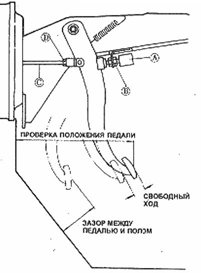
Adjusting the position and free play of the brake pedal
And - the stoplight switch; B - Switch locknut; C - Pusher; D - Pusher locknut