
MazBook.ru
English Русский
Български
Беларускі
Український
Српски
Hrvatski
Română
Polski
Slovenský
Magyar
• Bookmark • Sitemap • Contacts •   
Cars Opel Cars Ford Cars Volkswagen Cars Audi Cars Kia Cars Renault Cars Peugeot


Familia Capella Mazda3 Mazda6 CX-? Others Articles
Capella 3 (1982-1992, petrol) Capella 3 and 4 (1982-1992) Capella 4 (1987-1992) Capella 5 (1991-1997) Capella 6 (1997-2005, petrol)

Master cylinder — removal, overhaul and installation (Mazda Capella GC)

  • Home
  • Mazda Capella
  • Capella GC (1982-1992)
  • Chassis
  • Brake system
  • Master cylinder — removal, overhaul and installation
0
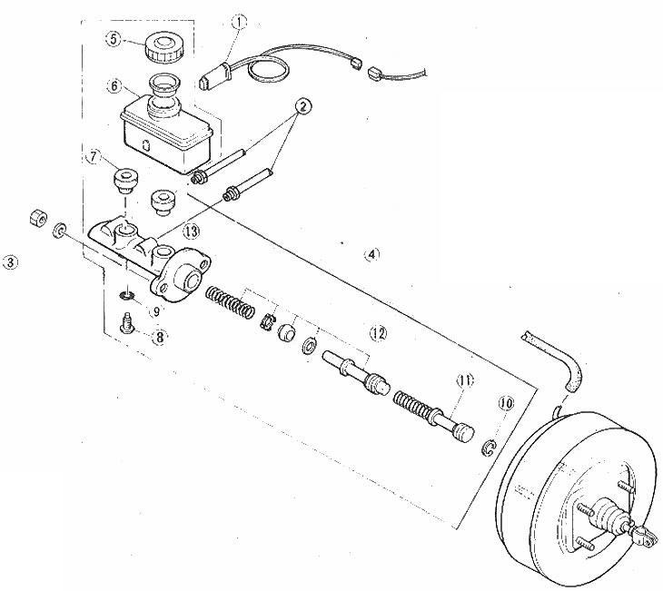
Master cylinder component locations

Master cylinder component locations

1. Liquid level sensor; 2. Torrens system tubes; 3. Nuts; 4. Assembling the master cylinder; 5. Tank lid; 6. Reservoir; 7. Bushings; 8. Secondary piston mounting screw; 9. O-ring seal; 10. Thrust ring; 11. Assembling the primary piston; 12. Assembling the secondary piston; 13. Master cylinder housing


1. Purchase a master cylinder rebuild kit. The kit contains all necessary replacement parts. It is very important that the rubber seals are installed correctly and fit tightly. Be careful not to allow grease or solvents to come into contact with rubber parts.

2. Cover surrounding painted surfaces where brake fluid may splash, as the fluid will dissolve the paint.

3. Disconnect the brake system pipes. Place a rag or newspaper under the master cylinder to absorb any spilled fluid. Disconnect the fluid level sensor connector, remove the two master cylinder mounting nuts and remove the master cylinder from the vehicle (photo).
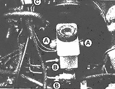
Master cylinder lock nuts (A), pipe connections (B) and fluid level sensor connector (C)

Master cylinder lock nuts (A), pipe connections (B) and fluid level sensor connector (C)


4. Drain any remaining liquid from the reservoir. Remove the reservoir by holding the master cylinder firmly and rocking the reservoir from side to side (photo).
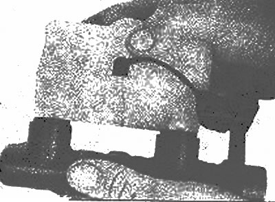
While holding the master cylinder, rock the reservoir from side to side to remove it

While holding the master cylinder, rock the reservoir from side to side to remove it


5. Place the master cylinder in a vertical position (front end down), press the primary piston and remove the thrust ring.

6. Remove the primary piston and discard it.

7. Using a wooden dowel, push out the secondary piston. Remove the O-ring and mounting screw.

8. Turn the master cylinder upside down and tap it with a wooden block to remove the secondary piston.

9. Remove the spring from the front end of the secondary piston.

10. Remove the secondary piston rear strut, cylinder cover seal, valve gaskets and two seals located on the rear of the piston.

11. Remove the bushings, cover and float from the tank.

12. Clean the master cylinder and inspect the cap for corrosion and damage. If such defects are detected, replace the master cylinder housing. The exception is cases where the defects are very minor.

13. Inspect the tank for cracks and the bushings for wear. Replace components as necessary.


14. Before assembly, lubricate all components with clean brake fluid.

15. Install the valve gasket onto the front end of the secondary piston. Install the seal on the piston (open end forward).
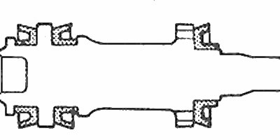
Installing secondary piston seals (shaded)

Installing secondary piston seals (shaded)


16. Install the center seal on the secondary piston (open end forward).

17. Install the secondary piston rear seal (open end to the back).

18. Place the O-ring on the secondary piston mounting screw.

19. Lubricate the primary and secondary pistons with clean brake fluid.

20. Push the secondary piston assembly into the cylinder using a wooden dowel. Compress the spring slightly and insert the set screw.

21. Insert the primary piston with the spring seat facing forward. Compress the spring slightly and install the thrust ring.

22. Lubricate the reservoir bushings, place the reservoir on a hard surface and install the reservoir body onto the master cylinder.

23. Install the float assembly into the tank.

24. It is recommended to check the clearance between the primary piston and the brake booster push rod. Manufacturers have created a special tool for this purpose, No. 49 11002 765. The gap size should be 0.41-0.61 mm (the vacuum in the amplifier is released). Adjustment is made by rotating the brake booster push rod, which is secured with a lock nut.
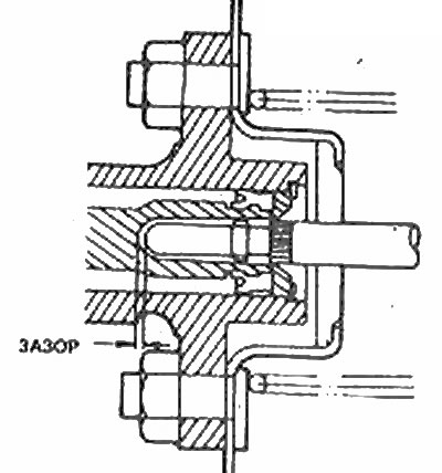


Clearance between the master cylinder and the brake booster pushrod

Clearance between the master cylinder and the brake booster pushrod


25. After installing the master cylinder, it is necessary to bleed the entire brake system. Bleeding can be done faster if you fill the master cylinder with fluid before installing it. Fill the reservoir with brake fluid and slowly push the piston all the way into the cylinder using a wooden dowel or screwdriver. Before releasing the piston, plug the holes under the brake system pipes to prevent air from entering the master cylinder. Repeat the procedure until bubble-free brake fluid flows out of the cylinder. While pumping, monitor the fluid level in the reservoir and do not let it empty.

26. Install the master cylinder in place and tighten the brake pipe nuts by hand.

27. Install the master cylinder lock nuts and tighten them securely.

28. Tighten the brake pipe nuts securely and connect the fluid level sensor connector.

29. Bleed all brakes (see Chapter 15).
This article is available at: russian, bulgarian, belarusian, ukrainian, serbian, croatian, romanian, polish, slovak, hungarian
This text was checked by: Evdokia Filimonova
Share with friends on social networks:

Previous
Capella 3 » Brake system
Next

Drum brake master cylinder — removal, overhaul and installation
Drum brake shoes — replacement
Brake disc — inspection, removal and installation
Disc brake caliper — rebuild
Disc Brake Caliper — removal and installation
Brake hoses and tubes — inspection and replacement
Parking brake — checking operation and adjustment
Brake pedal assembly — removal and installation
Parking brake assembly — removal and installation
Parking brake cables — removal and installation
More articles on repairing other Mazda models
Brake master cylinder and vacuum booster Mazda Familia 5 (1985-1989)
Master Brake Cylinder — Description Mazda3 BK (2003-2009)
Master Brake Cylinder — Description Mazda6 GG (2002-2008)
Removal and installation the clutch master cylinder Mazda CX-5KE (2012-2017)
Clutch master cylinder Mazda BT-50 (1) (2006-2011)
Link in different formats to this article
Comments and feedback from visitors
No comments yet


How much will 37 + 22 ?


Capella 6 (1997-2005, petrol) 
  • General information
  • Introduction to guide
  • User manual
  • Troubleshooting
  • Maintenance
  • Power unit
  • 4-cylinder engines
  • 6-cylinder engines
  • Engine overhaul
  • Cooling and ventilation
  • Power and exhaust systems
  • Engine electrics
  • Control system
  • Transmission
  • Mechanical gearbox
  • Automatic gearbox
  • Clutch and drive shafts
  • Chassis
  • Brake system
  • Car suspension
  • Steering
  • Body
  • Exterior (external elements)
  • Interior (internal elements)
  • Doors, windows and locks
  • Electrical equipment
  • Equipment and devices
  • Electrical circuits
Capella 5 (1991-1997) 
  • General information
  • User manual
  • Maintenance
  • Helpful hints
  • Power unit
  • Petrol engines 1.6 and 1.8
  • Petrol engines 2.0
  • 2.5 petrol engines
  • Overhaul engines 1.6 and 1.8
  • Overhaul engines 2.0 and 2.5
  • Diesel engine 2.0
  • Engine electrics
  • Cooling system
  • Air conditioner
  • Carburetor Nikki 30/34
  • Power system (1.6 and 1.8)
  • Power system (2.0 and 2.5)
  • Control system
  • Transmission
  • Mechanical gearbox
  • Automatic gearbox
  • Clutch and axles
  • Chassis
  • Brake system
  • Suspension and wheels
  • Steering
  • Body
  • Exterior (external elements)
  • Interior (internal elements)
  • Doors and windows
  • Electrical equipment
  • Equipment and devices
  • Electrical circuits
Capella 4 (1987-1992) 
  • General information
  • Introduction to manual
  • Vehicle specifications
  • Power unit
  • Engine repair
  • Lubrication system
  • Cooling system
  • Fuel system (carburetor)
  • Fuel injection (FE)
  • Fuel injection (DOHC)
  • Fuel system (diesel)
  • Ignition system
  • Transmission
  • Clutch
  • Gearbox
  • Drive shafts
  • Chassis
  • Front suspension
  • Rear suspension
  • Steering system
  • Brake system
  • Electrical equipment
  • Equipment and devices
  • Electrical circuits
Capella 3 and 4 (1982-1992) 
  • General information
  • User manual
  • Maintenance
  • Power unit
  • Gasoline engine
  • Engine overhaul (gasoline)
  • Diesel engine
  • Cooling and heating
  • Supply system
  • Ignition system
  • Emission reduction
  • Transmission
  • Clutch
  • Mechanical gearbox
  • Automatic gearbox
  • Drive shafts
  • Chassis
  • Brake system
  • Suspension and wheels
  • Steering
  • Body
  • Exterior (external elements)
  • Interior (internal elements)
  • Electrical equipment
  • Equipment and devices
  • Power devices
  • Electrical circuits
Capella 3 (1982-1992, petrol) 
  • General information
  • User manual
  • Maintenance
  • Troubleshooting
  • Late models
  • Power unit
  • Engine in car
  • Engine overhaul
  • Cooling and heating system
  • Fuel and exhaust system
  • Engine electrical system
  • Emission control system
  • Transmission
  • Mechanical gearbox
  • Automatic gearbox
  • Clutch and drive shafts
  • Chassis
  • Brake system
  • Suspension and wheels
  • Steering
  • Body
  • Exterior (external elements)
  • Interior (internal elements)
  • Electrical equipment
  • Equipment and devices
  • Lighting and lamps
  • Electrical circuits
MazBook.ru © 2018–2026 · Mobile version · Articles and news · Sitemap: EN BG BY UA RS HR RO PL SK HU · Feedback · Site search · Add to bookmarks Familia 5 (BF) · Familia 6 (BG) · Capella 3 (GC) · Capella 3 and 4 (GC) · Capella 4 (GD) · Capella 5 (GE) · Capella 6 (GF) · Mazda3 BK · Mazda6 GG · CX-5KE · Mazda 121 (3) · Mazda BT-50 (1) ·
By continuing to use the site, you agree to the use of cookies 🔐