


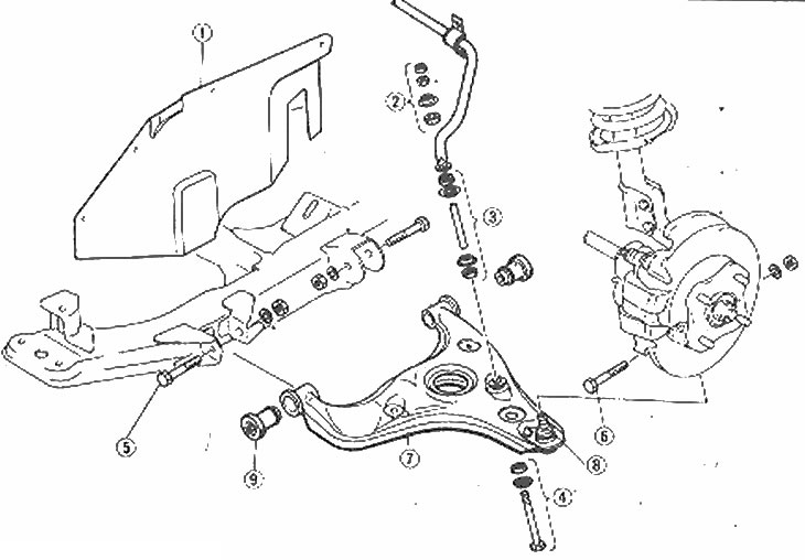
Front Lower Control Arm Installation Details
1. Mudguard; 2. Nuts, retainer and bushing; 3. Bushings, clamps and gaskets; 4. Bolt, retainer and bushing; 5. Lower arm mounting bolts and nuts; 6. Ball joint bolt and nut; 7. Lower arm; 8. Ball joint dust cover; 9. Rubber bushing
1. Raise the front of the car and support it on the jack stands.
2. If only one lower control arm was removed, disconnect only that end of the stabilizer bar. If both lower control arms have been removed, remove the entire stabilizer bar. Please contact Chapter 6.
3. Remove the wheel(s) and mudguard.
4. Remove the control arm bushing bolts that secure the control arm to the engine subframe.
5. Remove the ball joint-to-steering knuckle nut and then pry the ball joint away from the steering knuckle, using a pry bar if necessary.
6. Lower the control lever from the vehicle.
7. Inspect the control arm bushings for wear, cracking or excessive wear and the ball joints, clean the boot for damage and wear. Replacing the dust boots requires special tools and techniques, so control arm assembly should be performed by a dealer or a properly equipped workshop. The ball joint cannot be replaced without replacing the mount. New bushings can be installed by using appropriately sized pipes or sockets to press out the old bushings and insert the new ones. When connecting the bushings, use soapy water as a lubricant.
8. Installation of the lower control arm is carried out in reverse order.
Note: Do not tighten the lower control arm to the engine subframe bushing with bolts to specification until the vehicle is completely lowered to the ground and its full weight is supported by the suspension.
Based on website data (www.MazBook.ru)
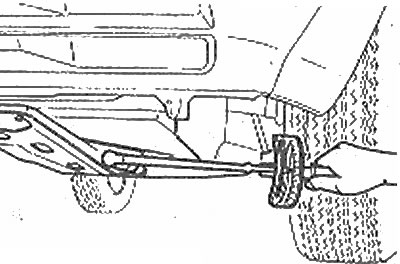
The control arm bolts must be tightened to the torque specified in the Specification after the vehicle weight has been lowered onto the suspension