


Contents: Checking and adjusting the ignition…⇓ Inspection and replacement of spark…⇓ Checking and replacing spark plug…⇓
Caution! On some models, when adjusting the ignition timing, it is mandatory to perform the procedures specified on the exhaust gas toxicity reduction information plate. The plate contains information on preliminary operations that must be performed before adjusting the ignition timing angle, as well as the necessary technical data.
Checking and adjusting the ignition timing
Perform the preliminary ignition timing adjustment procedures as shown on the VECI plate located under the hood.
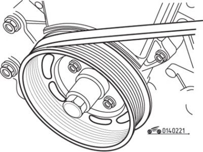
Figure 2.21. Location of marks for setting the ignition timing angle
Near the crankshaft pulley there is a plate with an indicator, which is designed to align the pulley's timing mark with it. The "T" mark corresponds to top dead center (TDC). The indicator plate is equipped with a 2° increment scale and a timing mark corresponding to your vehicle model. If there is no timing mark, count away from the "T" mark the required number of degrees BTDC as indicated on the VECI plate and mark this position on the plate. On some car models, instead of a plate, there is an ignition timing indicator and two notches on the pulley instead of one (figure 2.21). Do not use the top dead center (TDC) notch to set the ignition timing.
To make the mark on the pulley clearly visible when adjusting the ignition timing, mark it with chalk or paint.
Start the engine, warm it up to normal operating temperature and stop it. Turn off all electrical components and disconnect the electrical connector from the radiator fan.
With the ignition off, following the manufacturer's instructions, connect the stroboscope connector to the high-voltage wire of the spark plug of the first cylinder.
Start the engine, point the strobe light at the mark on the crankshaft pulley and determine which timing mark the notch on the pulley aligns with.
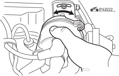
Figure 2.22. Directions of rotation of the distributor when adjusting the ignition timing
If the notch is not aligned with the required mark, loosen the distributor mounting bolt and turn it until the notch is aligned with the required installation mark (figure 2.22).
Tighten the distributor mounting bolt and recheck the ignition timing.
Stop the engine and disconnect the strobe light. Reconnect the spark plug wire of the first cylinder and the rest of the components that were disconnected.
Inspection and replacement of spark plugs
Use a jet of compressed air to clean the spark plug, which will prevent dirt from getting into the engine cylinder after the spark plug is removed.
Important! Manufacturers do not specify spark plug replacement intervals, but only indicate the need for regular inspection. In practice, spark plugs must be replaced during maintenance, even if the spark plugs are in good condition.
Remove the spark plug.
If spark plug replacement is necessary, use only spark plugs recommended for the engine.
The appearance of the removed spark plugs can be used to roughly assess the condition of the engine. A clean, white, plaque-free spark plug insulator indicates a too lean fuel-air mixture. This appearance of the candle also indicates that the candle is too hot (heat is removed from the central electrode slowly). It is necessary to adjust the composition of the fuel-air mixture or replace the spark plug.
Dry soot deposits are caused by a mixture that is too rich. If the coating is black and oily, the engine is worn out and needs to be checked and repaired. If the insulator is covered with a light brown coating, then the mixture composition is optimal and the engine is in good condition.
An interelectrode gap that is too large or too small, which changes the spark size, leads to a decrease in engine efficiency. The gap must always comply with technical requirements.
It is checked with a wire template or feeler gauge. The gap can be adjusted by bending the side electrode with a special tool. The central electrode must not be bent under any circumstances, as this may cause the insulator to break and the spark plug to fail.
Before installing the spark plug into the engine, check that the threads are clean and undamaged. Clean it if necessary. Apply a special non-stick compound to the spark plug threads.
Inspect the spark plugs for damage. If there are cracks in the insulator, the spark plug must not be used.
To screw in the spark plug a few turns, use a piece of rubber hose and insert the spark plug insulator into one end. The hose acts as a universal joint to align the spark plug with the threaded hole. If the spark plug is screwed in at an angle, the hose will turn on the spark plug insulator without damaging the threads. Screw the spark plug in a few turns, remove the hose, then screw in and tighten the spark plug with a wrench.
Use a torque wrench to tighten the spark plug. If a torque wrench is not available, tighten the spark plug no more than 1/4 turn past the point where the spark plug washer contacts the sealing surface.
Before connecting the high-voltage wire to the spark plug, check its condition.
Twist the high-voltage wire tip to the new spark plug until it fits securely onto the spark plug. Make sure the wire is located some distance away from the exhaust manifold.
Replace the remaining spark plugs in the same manner, replacing them one at a time to avoid mixing up the high-voltage wires.
Checking and replacing spark plug wires, distributor cap and rotor
The high voltage wires must be checked every time the spark plugs are installed. Begin a visual inspection with the engine running. In a darkened garage, start the engine and observe each wire. If an internal break in the wire is detected, an electric arc or spark will be visible at the location of the damage. If arcing occurs, replace the wire.
Start and cool the engine, then check the distributor cap and rotor.
Disconnect the cable from the negative battery terminal.
To avoid confusion, remove and inspect the high-voltage wires one by one.
Remove the spark plug tip with the high-voltage wire from the spark plug by pulling it up and turning it at the same time.
Do not remove the tip by pulling directly on the high voltage wire.
Check the inside of the tip for signs of corrosion, which is a white solid powder.
Install the tip with the high-voltage wire into place by pressing it and turning it at the same time until it locks firmly into place.
Using a clean cloth, wipe the high-voltage wire along its entire length, removing any dirt and grease. Check the wire for burns, cracks and other damage. Do not bend the wires too much, as the inner conductor may break. Using an ohmmeter, measure the resistance of the center conductor in each wire. Nominal resistance 16 kOhm/m.
Check the inside of the protective cover for signs of corrosion. Reconnect the high voltage wire.
Similarly, check the condition of the remaining high-voltage wires.
Remove the screws and remove the distributor cap. Check the inside of the lid for cracks, carbon tracks, burns, and loose contacts.
Remove the two screws and the distributor rotor. Check the rotor for cracks, carbon tracks, and burns on the side and central electrodes.
If any damage is present, replace the distributor cap and rotor. When replacing high-voltage wires, it is recommended to also replace the distributor cap and rotor.
Check the centrifugal timing advance adjuster for damage, corrosion, and damaged springs. While holding the distributor shaft, rotate the centrifugal governor housing and make sure that the governor weights move smoothly and that the spring tension is in the opposite direction.
Install the distributor cap, then connect the cable to the negative battery terminal.
Important! It is important to replace the wires one at a time and mark their connection points, as each wire ensures the correct firing order of the cylinders.