


- Carefully inspect the crankshaft for defects and measure the main and connecting rod bearing journals. The crankshaft main bearing journals and crankshaft connecting rod journals can be ground to accommodate shafts with smaller bearing shell sizes.
- Clamp the crankshaft between the centers of a lathe or place both outer main journals on prisms and check the runout on the middle main journals using a dial indicator. The runout of the gasoline engine shaft at a full revolution should be no more than 0.03 mm (figure 96). For a diesel engine, a tolerance of up to 0.05 mm is acceptable. Otherwise, the shaft must be replaced or repaired in a specialized workshop.
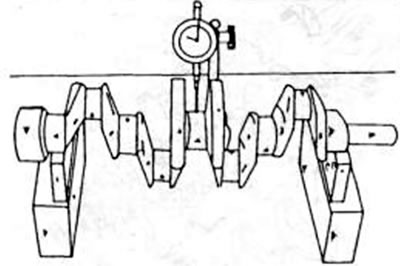
Figure 96. Measuring the crankshaft runout on the middle bearing.
Measuring the working clearance of the main and connecting rod bearings:
- thoroughly clean the bearing shells and bearing holes of the cylinder block and connecting rod;
- as shown in the picture 97, place a piece of plastic wire on all main bearing journals "Plastigagc" and install the main bearing cover together with the inserted liners. Tighten the bolts to the specified torque. After this, do not turn the shaft anymore;
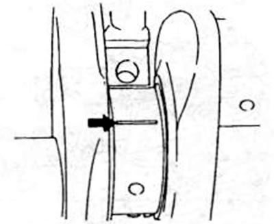
Figure 97. Measuring the working clearance of the crankshaft and connecting rod bearings. Wire "Ptastigage" apply in the specified place
- to check the working clearance of the bearings, place the connecting rod on the crankshaft journal and place a piece of wire on the upper side "Plastigage". Place the cover with the insert on and tighten the nuts to the specified tightening torque. Since the shaft can no longer rotate, the two connecting rod bearings located at the bottom dead center are also examined as needed. If the shaft has been removed for inspection, the connecting rods are positioned so that they can rotate independently after tightening;
- unscrew the covers from the main bearings; unscrew both caps of the connecting rod bearings one by one;
- Now measure using the template supplied with the kit "Plastigage", the widest point of the strip of the pressed piece of the drive (figure 98). If this number for the main and connecting rod bearings is not within the limit dimensions given in the tables of parameters and overall dimensions, then new bearing liners must be used, and it must be taken into account if the journals have already been ground previously, to determine the minimum permissible size;
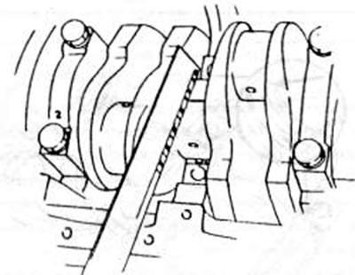
Figure 98. Measuring with a template pressed across the width of the wire "Plastigage".
- If the connecting rod bearing clearance is being checked, the crankshaft must be turned and both other main journals must be inspected and measured as described above.