


- Install a dial indicator using a bracket in front of the front of the cylinder block to position the dial indicator pin in the crankshaft end journal (figure 99).
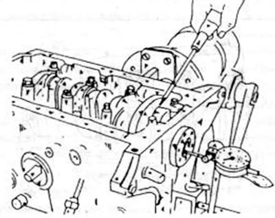
Figure 99. Measuring the axial clearance of the column shaft. Attach the dial indicator to the cylinder block and use a screwdriver to move the crankshaft back and forth
- Using a screwdriver, press the column shaft to one side, set the dial indicator to zero and press the shaft to the other side. The indicator reading is the crankshaft axial clearance and is recorded for subsequent assembly. If it is more than 0.30 mm, this must be taken into account during installation. The following must be observed:
— for a gasoline engine, the center bearing shells must have flanges on the sides and the width of the shells must be 0.25 greater than the nominal width; 0.50 mm to compensate for axial clearance;
— a diesel engine uses four half-discs, which are installed to the left and right of the middle bearing of the crankshaft. The discs have both nominal and oversized dimensions to compensate for axial clearance. When making adjustments, first replace both rear adjusting washers. If the gap still has not reached the required value, then the front washers also need to be replaced.
- If a dial indicator is not available, the axial clearance can be determined by inserting a sheet gauge between the crankshaft flange and the bearing.