


2.5.4. Measuring the operating clearance of the connecting rod bearing
This work is described in the section on the crankshaft.
2.5.5. Assembly of pistons and connecting rods
When assembling pistons and connecting rods, the following instructions must be observed:
- The arrow on the piston crown (new pistons have a "Vorn"-"F" marking near the piston ring bore) should point towards the front of the engine.
- On a standard engine, the oil hole in the connecting rod should point towards the front of the engine, i.e. after assembly, the piston and connecting rod should be positioned like this. as shown in Fig. 89. The DOHC engine does not have such a hole, and alignment is carried out in accordance with the figure 90. i.e. the "F" marking is located at the top if the connecting rod and bearing cap designation numbers are on the left side. A diesel engine's alignment is performed in the same way as a DOHC engine. This alignment is performed very carefully to avoid errors.
- The cylinder number markings on the connecting rods and bearing caps must match.
- Lubricate the piston pins well with oil and assemble the pistons with the connecting rods as follows:
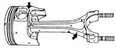
Figure 89. Make sure that the "F" marking on the piston and the oil hole in the connecting rod are in the indicated position after assembling the parts (standard engine 8 and 12 valves)
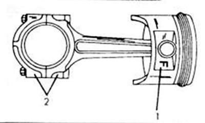
Figure 90. Piston and connecting rod alignment for a DOHC engine. The "F" mark (1) and connecting rod designations (2) must be located in the indicated location
— for a standard engine, press the piston pins into the pistons and connecting rods. Be careful not to damage the parts. The pressing pressure should be between 500 and 1500 kg. If the rings can be pressed in at a lower pressure, they or the connecting rods must be replaced. Since the pressure is very high, it would probably be best to have this work performed by a "Mazda" dealer;
— for a DOHC engine or a diesel engine, insert one of the safety spring rings into the piston rod eye and push the piston as far as possible with your thumb. After this, hit the piston pin with a stepped mandrel until it is positioned on the other side against the safety ring. Bend the second safety ring. Make sure both rings fit perfectly.
Check that the pistons can be easily moved up and down on the connecting rod after assembly. To do this, hold the piston with one hand and move the connecting rod with the other, as shown in the figure 91.
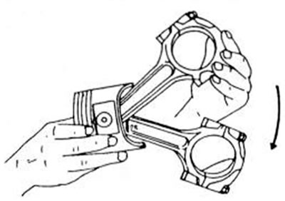
Figure 91. After assembling the piston and connecting rod, check the connecting rod as indicated for freedom of movement
Using your fingers, carefully insert the lower side part of the oil scraper piston ring, the distributor ring and the upper side ring from above into the lower groove of the piston. In doing so, it is important not to break individual parts of the ring. Since the ring is very flexible, it easily pops out of the groove. Figure 92 shows how this work can be easily carried out. The middle ring has a hole on one side. It should be facing upwards after installation. The position of the thermal gap does not matter.
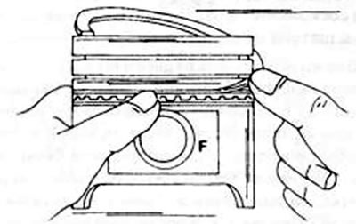
Figure 92. Installation of the middle spacer ring for the oil scraper piston ring. Press the ring on one side and carefully insert it into the groove.
Using a piston ring collet, insert the piston rings one by one into the grooves (see figure 80). Both piston rings can be mixed up and therefore it is necessary to look at their cross-sections before inserting them. The second piston ring on the outer side is sharply beveled upwards. In addition, both rings are marked on one side with a designation (designation letter "R"), and this designation must be visible from the piston bottom side after the ring is installed. For a diesel engine, the letters "N" can also be stamped.
(The original article is on: mazbook.ru)