
MazBook.ru
English Русский
Български
Беларускі
Український
Српски
Hrvatski
Română
Polski
Slovenský
Magyar
• Bookmark • Sitemap • Contacts •   
Cars Opel Cars Ford Cars Volkswagen Cars Audi Cars Kia Cars Renault Cars Peugeot


Familia Capella Mazda3 Mazda6 CX-? Others Articles
Capella 3 (1982-1992, petrol) Capella 3 and 4 (1982-1992) Capella 4 (1987-1992) Capella 5 (1991-1997) Capella 6 (1997-2005, petrol)

Installing pistons and connecting rods (Mazda Capella GD)

  • Home
  • Mazda Capella
  • Capella GD (1987-1992)
  • Power unit
  • Engine repair
  • Installing pistons and connecting rods
0
  • Lubricate the cylinder bores well.
  • Lay out all connecting rods according to cylinder numbers. The forward markings on the connecting rod and the piston side (with the letter "F") must face towards the engine belt pulley.
  • Distribute piston ring gaps at uniform intervals of 120° around the piston circumference. Figure 93 shows how the clearances relate to the piston rings on a gasoline engine. The numbers have the following meanings:
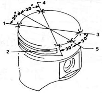
Figure 93. Location of piston ring gaps around the piston circumference. It is especially important…

Figure 93. Location of piston ring gaps around the piston circumference. It is especially important to observe the clearances of the oil scraper piston ring, which consists of three parts (gasoline engine). 1. Upper sealing ring.; 2. Lower bead ring (oil scraper piston ring); 3 Upper side ring (oil scraper piston ring); 4. Second piston ring; 5. Distribution ring (oil scraper piston ring)

— No. 1 — upper piston ring clearance;

— No. 2 — clearance of the lower side ring of the oil scraper piston ring;

— No. 3 — clearance of the upper side part of the oil scraper piston ring;

— No. 4 — second piston ring gap;

— No. 5 — clearance of the distribution ring for the oil scraper piston ring.


  • In a diesel engine, the arrangement of piston ring gaps is different:

— the clearance of the lower piston ring and the distributor ring for the oil scraper piston ring is shifted by 45° in relation to the piston pin hole and to the combustion chamber bath;

— exactly on the opposite side is the gap of the oil scraper piston ring. The gap of the second ring is located in the middle between the two gaps.
  • Place the tension band around the piston ring and press the ring into the groove. Check that it is pressed in perfectly.
  • Short lengths of rubber and plastic hoses should be pulled over the connecting rod studs to avoid scratching the holes. The nuts must be replaced all the time. because once installed, the nut loses its locking ability.
  • Turn the crankshaft until the two journals of the shaft are at bottom dead center.
  • Insert the connecting rod into the hole from above. To do this, lay the engine on its side so that the connecting rods can be brought to the main journals without scratching the holes or journals. The connecting rod bearing shells should already be in the connecting rods, with the protrusion in the groove.
  • When inserting, check again that the markings are directed as shown in figures 89 and 90.

Note: Diesel engine pistons must be preheated to 50-70°C before installation (electric stove).

  • Insert the piston until the rings slide into the hole one by one and the base of the connecting rod sits on the crankshaft journal.
  • Place the second bearing shell into the bearing cap and lubricate the shell well. Place the cover on the studs of the connecting rod base and press lightly. Of course, you need to make sure that the rubber sections of the hoses are removed. Make sure that the marks on the connecting rod and bearing cap are located on the same side, as you can make another mistake at the last moment.
  • Lubricate the mating surfaces of the nuts on the connecting rod caps.
  • Tighten the new connecting rod nuts alternately with a tightening torque of 66-70 Nm (standard and diesel engine) or 70-74 Nm (DOHC engine).
  • After installing the connecting rod, turn the crankshaft several times to immediately secure the clamps.
  • Rotate the crankshaft until both other crankshaft nuts are on the bottom side and install the remaining pistons and connecting rods in the same manner.
  • Recheck the markings on all pistons to ensure they are facing the correct direction.
  • Pattern as shown in figure 29, insert between the base of the connecting rod and the side of the crankshaft groove to measure the clearance between the side surface and the running side of the crankshaft. This is the axial clearance of the connecting rod bearing and it should not exceed 9.30 mm.
This article is available at: russian, bulgarian, belarusian, ukrainian, serbian, croatian, romanian, polish, slovak, hungarian
This text was checked by: Georgy Afanasyev
Share with friends on social networks:

Previous
Capella 4 » Engine repair
Next

Assembly of pistons and connecting rods
Pistons and connecting rods
Measuring cylinder bores
Pistons and connecting rods — removal and disassembly
Cylinder compression control
Cylinder block
Crankshaft and flywheel — inspection of parts
Crankshaft axial clearance control
Installing the crankshaft
Crankshaft sealing rings
More articles on repairing other Mazda models
Installing the cylinder head Mazda Familia 5 (1985-1989)
Installing the connecting rod bearing and cover Mazda3 BK (2003-2009)
Installing the connecting rod bearing and cover Mazda6 GG (2002-2008)
Checking the connecting rods of the cylinder block Mazda CX-5KE (2012-2017)
Connecting rods and pistons Mazda BT-50 (1) (2006-2011)
Link in different formats to this article
Comments and feedback from visitors
No comments yet


How much will 11 + 45 ?


Capella 6 (1997-2005, petrol) 
  • General information
  • Introduction to guide
  • User manual
  • Troubleshooting
  • Maintenance
  • Power unit
  • 4-cylinder engines
  • 6-cylinder engines
  • Engine overhaul
  • Cooling and ventilation
  • Power and exhaust systems
  • Engine electrics
  • Control system
  • Transmission
  • Mechanical gearbox
  • Automatic gearbox
  • Clutch and drive shafts
  • Chassis
  • Brake system
  • Car suspension
  • Steering
  • Body
  • Exterior (external elements)
  • Interior (internal elements)
  • Doors, windows and locks
  • Electrical equipment
  • Equipment and devices
  • Electrical circuits
Capella 5 (1991-1997) 
  • General information
  • User manual
  • Maintenance
  • Helpful hints
  • Power unit
  • Petrol engines 1.6 and 1.8
  • Petrol engines 2.0
  • 2.5 petrol engines
  • Overhaul engines 1.6 and 1.8
  • Overhaul engines 2.0 and 2.5
  • Diesel engine 2.0
  • Engine electrics
  • Cooling system
  • Air conditioner
  • Carburetor Nikki 30/34
  • Power system (1.6 and 1.8)
  • Power system (2.0 and 2.5)
  • Control system
  • Transmission
  • Mechanical gearbox
  • Automatic gearbox
  • Clutch and axles
  • Chassis
  • Brake system
  • Suspension and wheels
  • Steering
  • Body
  • Exterior (external elements)
  • Interior (internal elements)
  • Doors and windows
  • Electrical equipment
  • Equipment and devices
  • Electrical circuits
Capella 4 (1987-1992) 
  • General information
  • Introduction to manual
  • Vehicle specifications
  • Power unit
  • Engine repair
  • Lubrication system
  • Cooling system
  • Fuel system (carburetor)
  • Fuel injection (FE)
  • Fuel injection (DOHC)
  • Fuel system (diesel)
  • Ignition system
  • Transmission
  • Clutch
  • Gearbox
  • Drive shafts
  • Chassis
  • Front suspension
  • Rear suspension
  • Steering system
  • Brake system
  • Electrical equipment
  • Equipment and devices
  • Electrical circuits
Capella 3 and 4 (1982-1992) 
  • General information
  • User manual
  • Maintenance
  • Power unit
  • Gasoline engine
  • Engine overhaul (gasoline)
  • Diesel engine
  • Cooling and heating
  • Supply system
  • Ignition system
  • Emission reduction
  • Transmission
  • Clutch
  • Mechanical gearbox
  • Automatic gearbox
  • Drive shafts
  • Chassis
  • Brake system
  • Suspension and wheels
  • Steering
  • Body
  • Exterior (external elements)
  • Interior (internal elements)
  • Electrical equipment
  • Equipment and devices
  • Power devices
  • Electrical circuits
Capella 3 (1982-1992, petrol) 
  • General information
  • User manual
  • Maintenance
  • Troubleshooting
  • Late models
  • Power unit
  • Engine in car
  • Engine overhaul
  • Cooling and heating system
  • Fuel and exhaust system
  • Engine electrical system
  • Emission control system
  • Transmission
  • Mechanical gearbox
  • Automatic gearbox
  • Clutch and drive shafts
  • Chassis
  • Brake system
  • Suspension and wheels
  • Steering
  • Body
  • Exterior (external elements)
  • Interior (internal elements)
  • Electrical equipment
  • Equipment and devices
  • Lighting and lamps
  • Electrical circuits
MazBook.ru © 2018–2026 · Mobile version · Articles and news · Sitemap: EN BG BY UA RS HR RO PL SK HU · Feedback · Site search · Add to bookmarks Familia 5 (BF) · Familia 6 (BG) · Capella 3 (GC) · Capella 3 and 4 (GC) · Capella 4 (GD) · Capella 5 (GE) · Capella 6 (GF) · Mazda3 BK · Mazda6 GG · CX-5KE · Mazda 121 (3) · Mazda BT-50 (1) ·
By continuing to use the site, you agree to the use of cookies 🔐