


- Remove the oil level indicator.
- Unscrew the power steering pump console.
- Remove the ignition distributor. To do this, remove the spark plug wires one by one (the wires need to be marked with numbers). remove the vacuum hose between the carburetor and the distributor, remove the nut at the base of the distributor and take out the distributor.
- Remove the wiring of the exhaust gas recirculation system for the lead-free gasoline engine.
- Remove the drive belt of the brushless alternator after loosening the mounting clamp bolt and the retaining bolt.
- Remove the generator mounting bolts and generator clamp and remove the engine components.
- Remove thermostat housing bolts (from the distributor side) and remove the casing. Remove the seal.
- Remove the thermostat from the cylinder head holes.
- Unscrew the intake manifold together with the carburetor. Remove the manifold seal. Unscrew the exhaust pipe if it has not already been done.
- When removing the intake manifold of a pump-carburetor engine, you must first unscrew the branch pipe brackets.
- Unscrew the oil filter from the engine side. To do this, you need to use a filter key. If you don't have this type of key, you can tap the side of the filter with the end of a screwdriver and remove it using the handle. In any case, the filter must be replaced immediately after it has been removed. After unscrewing the filter, remove the oil cooler located underneath it.
- Unscrew all unnamed parts from the outside of the engine. After this, the distribution mechanism is removed. The condition of the drive belt must be checked before removal to determine whether it can be used again. If there is belt wear, it must be changed in the direction of travel. Figure 22 shows the individual parts of the distribution mechanism. Using this figure:
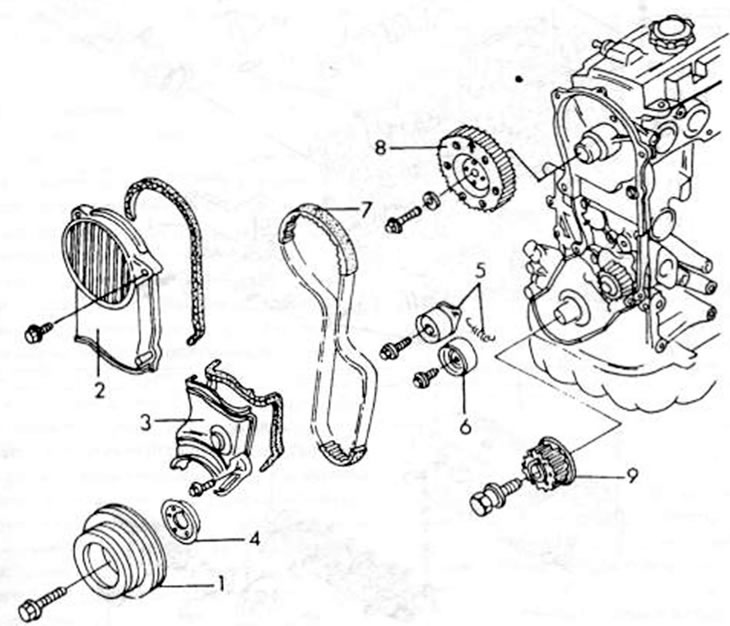
Figure 22. Timing belt components on the front of the engine. 1. Crankshaft belt pulley; 2. Upper timing belt cover; 3. Lower timing belt cover; 4. Guide cap; 5. Belt tensioner and spring; 6. Rotating roller of the toothed belt; 7. Drive belt; 8. Timing belt pulley; 9. Crankshaft drive wheel
- Remove the cylinder head cover.
- Unscrew the upper timing belt cover (2) and remove the seal.
- Unscrew the pulley (1) of the belt drive on the crankshaft from the crankshaft. To do this, insert a strong screwdriver into the teeth of the starter ring gear to prevent the engine from turning. Using two tire mounting blades, press the belt drive pulley away from the crankshaft. installed at two opposite points.
- Remove the lower cover (3) of the timing belt and screw in the seal. Remove the guide cap (4) from the crankshaft.
- Loosen the bolt in the middle of the timing belt tensioner (5), remove the springs and push the tensioner in as far as possible.
- Use a pencil to mark the direction of rotation of the belt on its outer side in case it is to be used again, and remove the belt from the guide pulleys. Keep belt away from oil, grease or other corrosive substances or liquids. In this case, you need to ensure that it does not bend or come into contact with oil, water or other harmful substances. It is best to hang the belt on a nail.
- If necessary, unscrew the rotating roller (6) for the toothed belt.
- Loosen the camshaft timing pulley bolts using a socket wrench. To do this, insert the rod into the groove of the belt pulley, as shown in the figure 23, so that it does not turn.
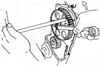
Figure 23.Kept the camshaft drive pulley from unscrewing the mounting bolt
- Remove the belt drive pulley (8) from the camshaft.
- Unscrew the front cover from behind the belt drive pulley and remove the seal.
- Unscrew the water pump from the cylinder block.
- Hold the flywheel again as indicated above and release the crankshaft drive wheel bolt. Carefully press the drive wheel (9) away from the crankshaft using two oppositely directed tyre levers or use a suitable puller for removal. Removing the cylinder head is carried out as follows. Figures 24 and 25 show the assembly drawings of the standard and 12-valve engine heads and can be used in the work:
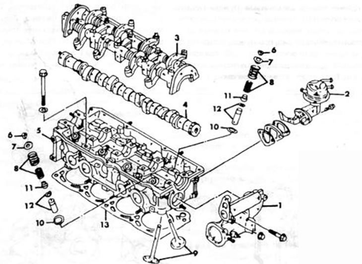
Figure 24. Cylinder head assembly drawing (8 valves): 1. Back cover; 2. Fuel pump; 3. Rocker arm axle; 4. Camshaft; 5. Cylinder head; 6. Rusk; 7. Valve spring plate; 8 Valve springs; 9. Valves; 10. Valve spring seat; 11. Valve stem sealing ring; 12. Valve guide and retaining ring; 13. Cylinder head seal
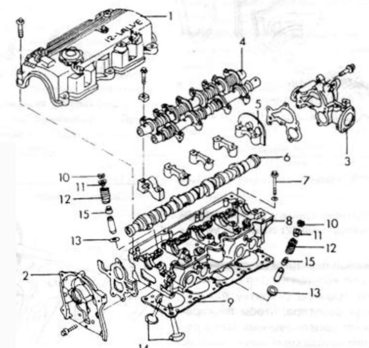
Figure 25. Cylinder head assembly drawing (12 valves): 1. Cylinder head cover; 2. Front casing; 3. Rear casing; 4 Rocker arm axis; 5. Camshaft bearing cap; 6. Camshaft; 7. Cylinder head bolt; 8. Cylinder head; 9. Cylinder head seal; 10. Valve cracker; 11. Upper valve spring plate; 12. Valve spring; 13 Lower valve spring plate; 14. Valve; 15. Valve stem seal
- Unscrew the rear cover from the cylinder head (where is the thermostat housing and distributor located?) and remove the seal.
- For a carburetor engine, loosen both bolts securing the fuel pump to the cylinder head and remove the pump. The pump should be tilted back slightly to allow the pump valve rocker arm to be moved away.
- Loosen the rocker arm bracket mounting bolts in several steps in the order shown in the figure 26, and turn it back a little, but leave it in the rocker arm. Pull both outer bracket bolts out on both sides as far as possible, grasp each one with one hand and remove the entire rocker arm mechanism from the head. As can be seen from both figures, the parts are removed from the head differently. With 12 valves, do not remove the hydraulic lifters; this should only be done if necessary. Put the shaft aside in case you need to disassemble it later.
(The article is copied from the website mazbook.ru)
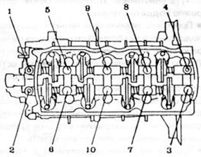
Figure 26. Rocker arm bearing bracket release sequence. On 8-valve engines, the bearing pillars serve as bearing caps for the camshaft. The 12-valve engine uses split covers.
- On a standard engine, the camshaft must be removed from the bearing holes in the cylinder head. For a 12-valve engine, remove the camshaft bearing caps one by one and lay them out in the assembly sequence. After this, remove the camshaft.
- Using Figures 27 and 28, loosen the cylinder head bolts in several steps in the order shown and remove the head. If the cylinder head does not come out, you can insert a screwdriver between the protrusion on the head and the cylinder block and press on the head. Never attempt to insert a screwdriver between the two sealing surfaces to press on the head.
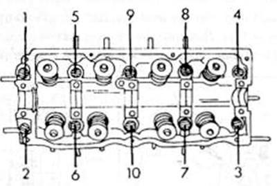
Figure 27. Sequence for releasing the cylinder head bolts on an 8-valve engine
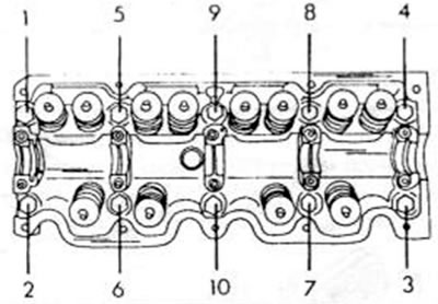
Figure 28. Sequence for releasing the cylinder head bolts on a 12-valve engine
- Remove the cylinder head gaskets.
- Turn the engine and unscrew the oil pan. The oil bath may be a very tight fit due to the sealant and may require some pressure to be applied. When using the pressing tool, care must be taken not to damage the oil bath flange. After removing the oil bath, take out the seal.
- Unscrew the oil inlet strainer from the bottom of the crankcase and remove the seal.
- How to grip the flywheel properly (with the oil pan unscrewed, you can insert a wooden block between the crank arm and the crankcase wall) and loosen the clutch bolts. Remove the clutch and take the driven pulley out of the flywheel. Do not handle the pulley with oily hands.
- Loosen the flywheel bolts and remove it (if necessary, tap gently with a rubber mallet). Make sure he doesn't fall.
- For vehicles with an automatic transmission, unscrew the torque converter drive pulley in a similar manner.
- Unscrew the engine mount clamp from the front wall of the engine.
- Unscrew the oil pump from the front of the cylinder block (see chapter 3.2).
- Unscrew the rear intermediate clutch disc of the engine.
- Unscrew the oil seal ring flange from the rear of the cylinder block and remove the seal. The seal can be carefully pried off with a screwdriver.
- Check the axial play of the four connecting rod bearings on the crankshaft before disassembling the crank mechanism. To do this, insert the 0.30 mm measuring probe as shown in the figure 29, between the wall of the crank pin and the connecting rod bearing. If the template can be inserted, the wear limit has been reached and appropriate measures must be taken, i.e. the connecting rods or, in the worst cases, also the crankshafts must be replaced.
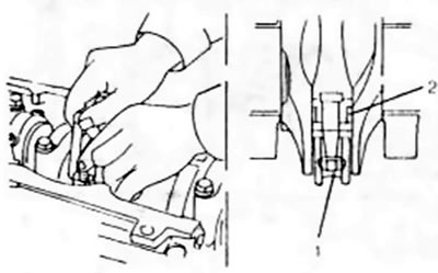
Figure 29. Checking the axial play of the connecting rod. 1. Connecting rod bearing cap; 2. Measuring probe (measurement location)
- Mark connecting rod bearing caps and connecting rods in order of cylinder numbers. To do this, use a center punch. One strike of the center punch on the first connecting rod, two strikes on the second, etc. The two connecting rod bearings must be at bottom dead center at all times when the cover is removed. To separate the cover, you need to hit both studs alternately with a plastic hammer, i.e. hit the connecting rods inward. The engine should lie on its side.
- Place short pieces of rubber or plastic hoses over the connecting rod studs (to avoid damaging the holes) and remove the connecting rods together with the pistons from the cylinder holes one by one. If there is a ring of oil carbon deposits on the top of the cylinder bore, it can be carefully scraped off with a scraper. In this case, it is necessary to ensure that the bearing liners and caps are immediately reattached to the corresponding connecting rods.
- After removing the other two components, lay out the pistons and connecting rods in the assembly sequence. To mark the pistons, you can carefully apply the cylinder number to the oil deposits with a sharp object, but without damaging the bottom of the cylinder.
- Measure the axial play of the crankshaft and record its value (chapter 2.7.2).
- Remove the crankshaft. In this case, the bearing caps are marked with numbers (No. 1 on the belt pulley cover, No. 5 on the side of the flywheel). Loosen the cap bolts in several steps and remove the caps. Remove the crankshaft and the remaining bearing shells from the crankcase and place them together with the other shells and covers.