
MazBook.ru
English Русский
Български
Беларускі
Український
Српски
Hrvatski
Română
Polski
Slovenský
Magyar
• Bookmark • Sitemap • Contacts •   
Cars Opel Cars Ford Cars Volkswagen Cars Audi Cars Kia Cars Renault Cars Peugeot


Familia Capella Mazda3 Mazda6 CX-? Others Articles
Capella 3 (1982-1992, petrol) Capella 3 and 4 (1982-1992) Capella 4 (1987-1992) Capella 5 (1991-1997) Capella 6 (1997-2005, petrol)

Disassembling a DOHC engine (Mazda Capella GD)

  • Home
  • Mazda Capella
  • Capella GD (1987-1992)
  • Power unit
  • Engine repair
  • Disassembling a DOHC engine
0
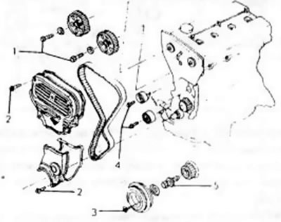
Disassembly of this engine is carried out in the same way as described for the standard engine. The difference, of course, is in the steering due to the installation of two camshafts. The following description therefore covers only the removal of the timing gear and the timing head. First of all, you need to remove the parts of the distribution mechanism, using the drawing 30:

Figure 30. Control parts of a twin overhead cam engine: 1. Crankshaft timing pulley; 2. Upper…

Figure 30. Control parts of a twin overhead cam engine: 1. Crankshaft timing pulley; 2. Upper timing belt guard; 3. Lower timing belt guard; 4. Guide cap; 5. Belt tensioner and spring; 6. Timing belt drive roller; 7. Toothed belt; 8. Suitable camshaft wheels; 9. Crankshaft drive wheel

  • Hold the crankshaft from turning and loosen the belt pulley bolts. Remove the belt drive pulley (1).
  • Unscrew the upper (2) and lower (3) timing belt protective covers and remove both seals.
  • Remove the guide cap (4) from the end of the crankshaft.
  • Loosen the bolt in the middle of the control belt tensioner (5), remove the spring and push the tensioner in as far as possible.
  • Use a pencil to mark the direction of rotation of the belt on its outer side in case it is to be used again, and remove the belt from the drive pulleys. Keep belt away from oil, grease and other corrosive substances or liquids. In this case, you need to ensure that it does not bend or come into contact with oil, water or other harmful substances. It is best to hang the belt on a nail.
  • If necessary, unscrew the drive roller (6) for the toothed belt.
  • Loosen the bolts of both camshaft timing pulleys using a socket wrench. To do this, insert the rod into the groove of the belt pulley, as shown in the figure 31. so that it does not turn.
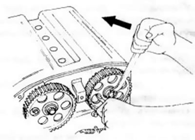
Figure 31. Releasing the drive wheel bolts on the DOHC engine

Figure 31. Releasing the drive wheel bolts on the DOHC engine


  • Remove the belt drive pulley (8) from the camshaft.
  • Unscrew the front cover from behind the belt drive pulley.
  • Hold the flywheel again as described above and release the crankshaft drive wheel bolt. Carefully press the drive wheel (9) away from the crankshaft using two oppositely directed tyre levers or use a suitable puller for removal.
  • Removal the cylinder head is carried out as follows. Figure 32 shows the assembly drawing of the cylinder head and can be used in the work:
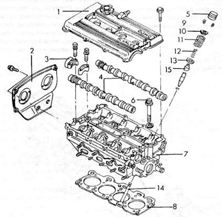
Figure 32. Assembly drawing of the DOHC engine cylinder head. 1. Cylinder head cover; 2. Protective…

Figure 32. Assembly drawing of the DOHC engine cylinder head. 1. Cylinder head cover; 2. Protective cover; 3. Camshaft bearing cap; 4. Camshaft; 5. Hydraulic pusher; 6. Cylinder head bolt; 7. Cylinder head; 8. Cylinder head seal; 9. Valve crackers; 10. Upper valve spring plate; 11. Outer valve spring; 12. Inner valve spring; 13. Lower valve spring; 14. Valve; 15. Valve stem sealing ring


(The article is copied from the resource: «www.MazBook.ru»)
  • Gradually loosen the camshaft bearing cap fastening bolts (3) and remove both camshafts from the cylinder head.
  • Remove the hydraulic tappets (5) and lay them out in the assembly sequence.
  • Using the drawing 33. Loosen the cylinder head bolts in the order shown in several steps. If the cylinder head does not come out, you can insert a screwdriver between the protrusion on the head and the cylinder block and press on the head. Do not, under any circumstances, attempt to insert a screwdriver between the sealing surfaces to press on the head.
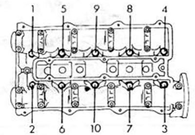
Figure 33. Sequence for releasing the cylinder head bolts on a DOHC engine

Figure 33. Sequence for releasing the cylinder head bolts on a DOHC engine

  • Remove the cylinder head gasket.
  • The remaining cylinder block now looks like an engine block with a camshaft and can be handled accordingly. In chapter 2.2.1 the remaining disassembly work is described.
This article is available at: russian, bulgarian, belarusian, ukrainian, serbian, croatian, romanian, polish, slovak, hungarian
This text was checked by: Georgy Afanasyev
Share with friends on social networks:

Previous
Capella 4 » Engine repair
Next

Gasoline engine (except DOHC engine)
Disassembling the engine
Removal and installation the engine
Disassembling a diesel engine
Engine assembly
Removal the cylinder head
Disassembling the cylinder head
Inspection of the cylinder head
More articles on repairing other Mazda models
Disassembling the engine Mazda Familia 5 (1985-1989)
Engine number Mazda3 BK (2003-2009)
Engine number Mazda6 GG (2002-2008)
Disassembling and assembling the engine Mazda CX-5KE (2012-2017)
Starting the engine from an auxiliary battery Mazda 121 (3) (1996-2003)
Link in different formats to this article
Comments and feedback from visitors
No comments yet


How much will 50 + 31 ?


Capella 6 (1997-2005, petrol) 
  • General information
  • Introduction to guide
  • User manual
  • Troubleshooting
  • Maintenance
  • Power unit
  • 4-cylinder engines
  • 6-cylinder engines
  • Engine overhaul
  • Cooling and ventilation
  • Power and exhaust systems
  • Engine electrics
  • Control system
  • Transmission
  • Mechanical gearbox
  • Automatic gearbox
  • Clutch and drive shafts
  • Chassis
  • Brake system
  • Car suspension
  • Steering
  • Body
  • Exterior (external elements)
  • Interior (internal elements)
  • Doors, windows and locks
  • Electrical equipment
  • Equipment and devices
  • Electrical circuits
Capella 5 (1991-1997) 
  • General information
  • User manual
  • Maintenance
  • Helpful hints
  • Power unit
  • Petrol engines 1.6 and 1.8
  • Petrol engines 2.0
  • 2.5 petrol engines
  • Overhaul engines 1.6 and 1.8
  • Overhaul engines 2.0 and 2.5
  • Diesel engine 2.0
  • Engine electrics
  • Cooling system
  • Air conditioner
  • Carburetor Nikki 30/34
  • Power system (1.6 and 1.8)
  • Power system (2.0 and 2.5)
  • Control system
  • Transmission
  • Mechanical gearbox
  • Automatic gearbox
  • Clutch and axles
  • Chassis
  • Brake system
  • Suspension and wheels
  • Steering
  • Body
  • Exterior (external elements)
  • Interior (internal elements)
  • Doors and windows
  • Electrical equipment
  • Equipment and devices
  • Electrical circuits
Capella 4 (1987-1992) 
  • General information
  • Introduction to manual
  • Vehicle specifications
  • Power unit
  • Engine repair
  • Lubrication system
  • Cooling system
  • Fuel system (carburetor)
  • Fuel injection (FE)
  • Fuel injection (DOHC)
  • Fuel system (diesel)
  • Ignition system
  • Transmission
  • Clutch
  • Gearbox
  • Drive shafts
  • Chassis
  • Front suspension
  • Rear suspension
  • Steering system
  • Brake system
  • Electrical equipment
  • Equipment and devices
  • Electrical circuits
Capella 3 and 4 (1982-1992) 
  • General information
  • User manual
  • Maintenance
  • Power unit
  • Gasoline engine
  • Engine overhaul (gasoline)
  • Diesel engine
  • Cooling and heating
  • Supply system
  • Ignition system
  • Emission reduction
  • Transmission
  • Clutch
  • Mechanical gearbox
  • Automatic gearbox
  • Drive shafts
  • Chassis
  • Brake system
  • Suspension and wheels
  • Steering
  • Body
  • Exterior (external elements)
  • Interior (internal elements)
  • Electrical equipment
  • Equipment and devices
  • Power devices
  • Electrical circuits
Capella 3 (1982-1992, petrol) 
  • General information
  • User manual
  • Maintenance
  • Troubleshooting
  • Late models
  • Power unit
  • Engine in car
  • Engine overhaul
  • Cooling and heating system
  • Fuel and exhaust system
  • Engine electrical system
  • Emission control system
  • Transmission
  • Mechanical gearbox
  • Automatic gearbox
  • Clutch and drive shafts
  • Chassis
  • Brake system
  • Suspension and wheels
  • Steering
  • Body
  • Exterior (external elements)
  • Interior (internal elements)
  • Electrical equipment
  • Equipment and devices
  • Lighting and lamps
  • Electrical circuits
MazBook.ru © 2018–2026 · Mobile version · Articles and news · Sitemap: EN BG BY UA RS HR RO PL SK HU · Feedback · Site search · Add to bookmarks Familia 5 (BF) · Familia 6 (BG) · Capella 3 (GC) · Capella 3 and 4 (GC) · Capella 4 (GD) · Capella 5 (GE) · Capella 6 (GF) · Mazda3 BK · Mazda6 GG · CX-5KE · Mazda 121 (3) · Mazda BT-50 (1) ·
By continuing to use the site, you agree to the use of cookies 🔐