


When disassembling, first remove the external parts in the following order: vacuum pump and drive belt, air intake housing, exhaust pipe heat shield, exhaust pipe, intake manifold, brushless alternator and drive belt, oil filter and oil filter housing, radiator, exhaust pipe mount, alternator suspension clamp. The gas distribution mechanism is now removed, guided by the drawing 34, in the following sequence:
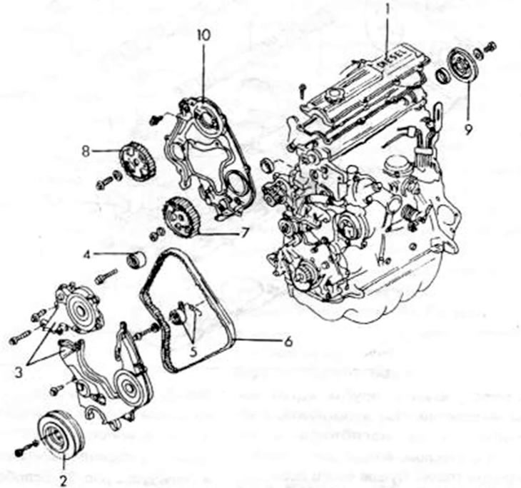
Figure 34. Diesel engine control system components 1. Cylinder head cover; 2. Crankshaft belt pulley; 3. Timing belt protective cover; 4. Drive roller; 5 Tensioner; 6. Drive belt; 7. Drive wheel. High pressure fuel pump; 8. Camshaft drive wheel; 9. Rear flywheel of the camshaft belt drive; 10. Inner protective cover
- Remove the cylinder head cover.
- Unscrew the crankshaft belt drive pulley (2) from the crankshaft. To do this, insert a strong screwdriver between the teeth of the starter ring gear to lock the engine against turning. Using two oppositely directed tire mounting blades, press the belt drive pulley away from the crankshaft.
- Remove the left and right drive belt covers (3).
- Loosen the bolt in the middle of the belt tensioner (5), remove the springs, push the device inward as far as possible and tighten the bolt in this place again.
- Turn the crankshaft until the drive wheel is in the position shown in the figure 35.
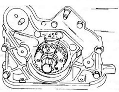
Figure 35. Aligning the drive wheel after removing the control.
- Mark the direction of rotation of the timing belt on its outer side in case it is to be used again, and remove the belt from the drive wheel. Keep belt away from oil, grease or other corrosive substances or liquids. In this case, you need to ensure that it does not bend or come into contact with oil, water or other harmful substances. It is best to hang the belt on a nail.
- If necessary, unscrew the drive roller (4) for the toothed belt.
- Loosen the high pressure fuel pump drive wheel bolts. First, check the wheel installation. Both injection time marks (1) must be as shown in the figure 36, located opposite each other. To hold the drive wheel in this position, screw two 35-40 mm long bolts into the wheel. These bolts fit into the threaded holes in the mounting bracket and lock the wheel in this position. Then loosen the bolts.
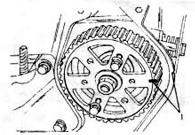
Figure 36. Aligning the high pressure fuel pump drive wheel before both bolts are tightened to lock the wheel.
- Using a puller, remove the high-pressure fuel pump drive wheel in the same way as shown for the camshaft in the figure 38.
- Loosen the camshaft timing belt pulley bolts using a socket wrench. At the same time, hold the camshaft as shown in the figure 37. If an adjustable wrench is not available, a 29mm socket wrench can be used. Like the pump gear, the camshaft sprocket must also be removed using a two-jaw puller, which is screwed into the threaded hole in the drive sprocket, as shown in Figure 38.
- Hold the camshaft again as shown in the figure 37. and remove the rear pulleys (9). Remove the belt drive pulleys.
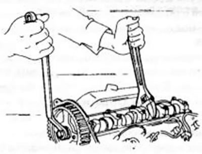
Figure 37. Releasing the camshaft drive wheel bolts.
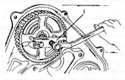
Figure 38. Removing the camshaft drive wheel. The high pressure fuel pump wheel is removed in the same way
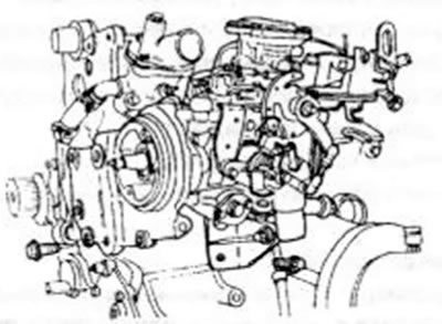
Figure 39. High pressure fuel pump in installed condition.
- Remove the engine mount and drive wheel from the front of the engine.
- Remove the fuel line and high pressure fuel pump. Remove the pump together with the holder. The injection control system does not necessarily have to be installed in this way.
- From the engine side, unscrew the oil level indicator outlet pipe and remove it together with the rubber hose.
- Remove the fuel line.
- Remove the water line and water pump. Removing the cylinder head is carried out as follows. Figure 40 shows a mounting drawing of the head that can be used when working:
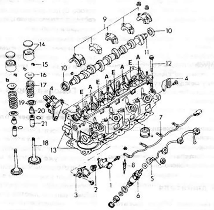
Figure 40. Assembly drawing of the cylinder head of a diesel engine 1. Thermostat cover; 2. Thermostat; 3. Thermostat cover; 4. Engine clamp; 5. Oil drain pipe; 6. Nozzle; 7. Tire; 8. Glow plug; 9. Camshaft bearing cap; 10. Oil seal; 11. Camshaft; 12. Cylinder head bolt; 13. Cylinder head and seal; 14. Pusher and installed disc; 15. Conical valve cracker; 16. Upper valve spring plate; 17. Valve spring; 18. Valve; 19. Lower valve spring plate; 20. Valve stem sealing ring; 21. Valve guide and fuse
- Unscrew the thermostat housing cover (1), remove the thermostat (2) and unscrew the housing (3).
- Unscrew both engine clamps (4).
- After releasing the nuts, remove the oil drain pipe (5).
- Unscrew the nozzle (6).
- Unscrew the glow plug bus and remove it.
- Remove the candles (8).
- Gradually loosen the camshaft bearing cap mounting bolts in two or three steps. In this case, you need to start from the edges of the head and move towards the middle.
- Remove the camshaft and both oil seal rings (10) - front and rear.
- Loosen the cylinder head bolts in an inward direction. The release diagram corresponds to the figure 27, just need to start on the other side of the head. Remove the head. If the head does not come off, you can insert a screwdriver between the tab on the cylinder head and the cylinder block to push on the head.
- Remove the cylinder head gasket.
- Remove the valve tappets and their installation discs (14) one by one and put them in the installation order. When further disassembling, proceed as described in chapter 2.2.1 for gasoline engine
The article is copied from the resource: MazBook
Caution: Never remove the cylinder head if the engine temperature exceeds 40°C.