


- Dry the blind holes and insert the inserts with lubrication grooves and a guide protrusion into the groove of the blind holes. Lubricate the bearings well and make sure that no oil gets on the rear part. Install the gasoline engine flange bearings onto the center bearing as shown in the figure 100. The position of the groove can be seen in the figure. For a diesel engine, install adjusting washers on the center bearing. The projections of the lower half-discs enter the grooves. The walls of the half-discs with lubrication grooves on both sides extend outward. At all times, it is necessary to ensure that the bearing shells and guides fit precisely into the grooves.
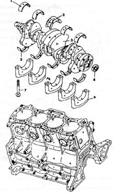
Figure 100. View of the crankshaft with bearings 1. Conventional bearing shell; 2. Thrust bearing insert with flanges; 3. Crankshaft; 4. Crankshaft centering bearing; 5. Main bearing shell; 6. Main bearing cover; 7. Main bearing cover bolt
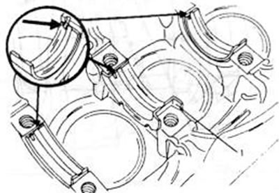
Figure 101. The middle flange bearing (1) on a gasoline engine is installed in the manner shown. The cutout in the circle shows the protrusion for guiding the bearing shell.
- Carefully lift the crankshaft with the liners. If the connecting rods are still in the cylinder block, you need to guide the connecting rod bearings onto the connecting rod journals of the crankshaft.
- Place the lower bearing shells into the corresponding crankshaft bearing caps (protrusions into the groove) and lubricate the surfaces well. Reinstall the bearing shell with flanges onto the center bearing (gasoline engine) or half-discs on the sides of the middle cover.
- Place the covers on the crankcase and hit them with a rubber or plastic hammer. The arrows on all covers must point towards the front of the engine as shown in the figure 102.
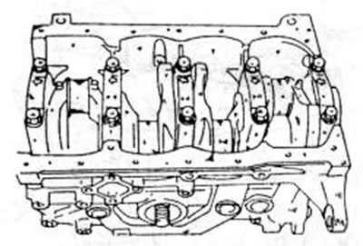
Figure 102. All arrows on the top of the crankshaft bearing cap must point in the direction shown.
[For details, see the website: www.MazBook.ru]
- Tighten the cover bolts from the middle to the edges in several steps with the tightening torque specified for the corresponding engine. After tightening the caps, rotate the crankshaft several times to secure the clamp. To do this, you need to temporarily place the crankshaft drive gear on the shaft with a segment key and screw on the belt drive pulley. Axial clearance. Check again as already described in chapter 2.7.2 (see also the picture 99). If the clearance was too large from the start, use middle bearing shells or adjusting washers, depending on the engine type.
- If the engine centering bearing with a stepped gearbox was removed, then the new bearing must be driven in with a piece of pipe of a suitable diameter. In this case, the piece of pipe must be placed against the outer bearing ring, as shown in the figure 103.
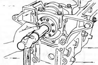
Figure 103. Clogging of the clutch shaft centering bearing at the end of the crankshaft.
- Install pistons and connecting rods as described in chapter 2.5.6.
- Install both oil seal rings (chapter 2.7.4).
- Bolt on the rear engine intermediate plate.
- Install the crankshaft drive gear with the key.
- Install the flywheel. Hold the crankshaft by inserting a wooden block between the crank arms and the crankcase wall, and tighten the bolts to the specified tightening torque. If an automatic transmission is installed, mount the driven disk in the same way.
- Clutch (if correct) should be attached in accordance with the marking on the flywheel. The driven clutch disc must be perfectly centered (chapter 10.3). Tighten the bolts evenly in a crosswise direction to the specified tightening torque.
- Install the oil pump (see chapter 3.2).
- Install the oil pan (chapter 3.1).
- All other work should be carried out in the reverse order of dismantling.
- Finally, install the cylinder head and timing mechanism as described in the relevant chapter.