


2.4.6.1. Standard engines
The valve clearance on these engines should definitely be set when the engine is warm. The coolant should be at 35°C. This can be checked with a thermometer if you are unsure, or you can touch the cylinder head, which should be slightly warm. To turn the engine, the appropriate key is placed on the crankshaft drive gear bolt. Do not use camshaft gear bolts for this purpose (if there was no drive gear cover, it would be easy to try to do this). Valve clearance can be measured from the valve side, i.e. between the end of the valve stem and the mounting bolt in the rocker arm, or between the cams and the opposite end of the rocker arm, but the resulting clearances are different and cannot be confused. When measuring the clearance from the camshaft side, the camshaft lobes for the corresponding cylinder and corresponding valve should point upwards, i.e. the flat side of the cam is located opposite the rocker arm. The installation sequence is arbitrary, but the piston of the first cylinder must be set to the position corresponding to the ignition timing, with both valves closed. Install the current valves and then crank the engine, after which the remaining valves can be installed. The valves are installed as follows, however, the inlet and outlet valves are positioned as shown in the figure 76. Turn the engine until the piston of the first cylinder reaches top dead center. All valves have clearance and the notch on the crankshaft timing pulley should be aligned with zero on the adjustment scale.
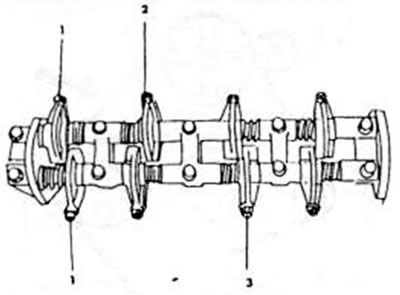
Figure 76. Sequence of setting valve clearances if the piston of the first cylinder reaches top dead center. The upper chambers are graduation chambers.
- Referring to Figure 76, install the valves marked with an arrow.
- Turn the engine one revolution until the notch is at zero again.
- Using the drawing 76, install the remaining valves.
- To install the valves, loosen the valve set bolt locknuts with a socket wrench and reposition the set bolts so that a plate template can be inserted between the end of the valve stem and the rocker arm or the cam and rocker arm. A 0.3 mm template is used on the valve stems, a 0.2 mm template is used on the cams.
- After tightening the lock nuts, check the valve clearance again, as it may happen that the bolts turn when tightening the nuts. A good sign that the gap has been set correctly is that the inserted template bends when pressure is applied. and then straightens up.
2.4.6.2. Diesel engine
- The valve clearance of a diesel engine is checked or set when the engine is cold. If the engine is installed, the cylinder head cover must be removed.
- Turn the engine so that the piston of the first cylinder is at top dead center during compression. Both cams then assume the position shown in the figure 77.
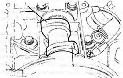
Figure 77. Position of the intake (1) and exhaust (2) valve cams if the piston of the first cylinder reaches top dead center during compression
[Information copied from the portal: mazbook.ru]
- In this position, measure the clearance of the intake valves of cylinders No. 4 and No. 2 and the clearance of the exhaust valves of cylinders No. 1 and No. 3, as shown in the figure 78. Sensors with a thickness of 0.20-0.30 mm are used for intake valves and 0.30-0.40 mm for exhaust valves. The clearance size of each valve is indicated in the table.
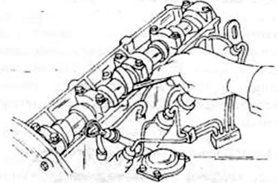
Figure 78. Checking valve clearance in a diesel engine
Turn the engine so that both cams of the fourth cylinder are in the position shown in the figure 77, i.e. the piston of this cylinder was at top dead center during compression, measure the clearances of the exhaust valves of the 3rd and 4th cylinders. Write down the values.
From the results obtained, you can now see whether adjustment is necessary. If one of the valve clearances is outside the specified values, it is adjusted by replacing the adjusting washer on the top side of each tappet with a stronger or weaker one. This requires a tool that can push the tappet into the hole against the resistance of the valve spring to locate the washer. If such a special tool is available, proceed as follows:
- turn the camshaft until the cam lobe of the adjustable valve points upward;
- using a screwdriver as shown in the picture 79, turn the pusher so that the groove produced is directed towards the branch pipe;
- insert the special tool shown in the picture 79 until the adjusting washer is released and can be removed;
- determine the thickness of the washer. The washer has a number indicating its thickness. For example, "3825" means the washer is 3.825 mm thick. Using the thickness of the inserted washer, calculate the measured gap and determine the recommended clearance. For intake valves, the average clearance is 0.25 mm, and for exhaust valves, 0.35 mm. This determines the thickness of the new washer. The following example shows the calculation:
The thickness of the removed washer is 4.00 mm
Measured gap - + 0.30 mm
The required gap is 0.25 mm
The thickness of the new washer is 4.05 mm
- there are 25 different thicknesses of adjusting washers available, from 3.40 to 4.60 mm, with a difference of 0.05 mm;
- insert a new washer in place of the existing one and check the gap again, now it should be within the tolerances;
- adjust all valves in the manner described above. Finally, reinstall the cylinder head cover.
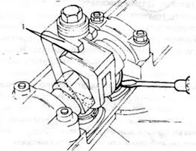
Figure 79. Using special tools (1) to press in the tappets. Turn the pusher with a screwdriver to move the slot to the outside.