
2. Lay out the gauge sets next to the pistons and make sure that the pistons and rings associated with each cylinder remain in the set until the end of the assembly.
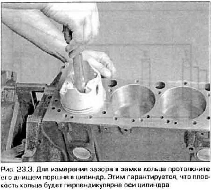
3. Insert the top ring into cylinder #1 and push it into the cylinder with the bottom of the piston until the ring is at BDC (pic. 23.3).
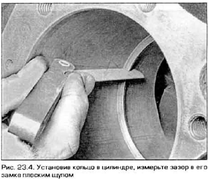
4. Measure the gap in the ring lock. picking up a probe of the desired thickness, which enters the gap with some friction (see fig. 23.4). Compare your result with technical data at the beginning of the chapter. If the clearance is less or greater than the allowable value, measure it again to be sure.
5. If the gap is too small, it can be finished. However, the possibility of correcting the gap in this way depends on what material the ring is made of and what it is coated with. Read the instructions that come with the ring kit carefully.
6. A large gap is not as dangerous as a small one, unless, of course, it exceeds the maximum allowable value. To be sure, double-check the gap again to make sure that you purchased the rings of the size you need. If you still consider it necessary to correct the gap with a file, then clamp the file in a vise (not a ring) in an upright position, grease the top side of the vise jaws, slide the ring lock onto the file and slide the rings back and forth across the file, pressing the ring against the vise. Having filed a little ring, check the gap again, if necessary, saw it further. After the gap has entered the tolerance, remove the burrs formed during sawing with a file.
7. Repeat this procedure for all rings of the first cylinder, and then for the remaining cylinders. During and after the check, do not confuse the rings - they must be subsequently inserted into the cylinder in which they were checked.
8. After checking and adjusting the gaps, the rings can be inserted into the piston grooves.
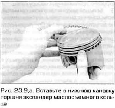
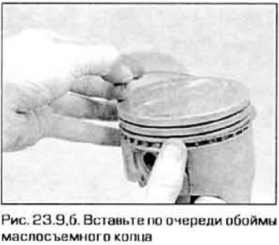
9. The bottom is installed first (oil scraper) ring. It consists of three parts. Insert an expander into the lower groove of the piston (pic. 23.9, a). If the expander has a locking lug, it must fit into the hole in the piston groove. Then insert the lower race of the ring. Do not use a ring setting tool for this purpose - the clip is easily damaged. Instead, insert one end of the ring into the gap between the expander and the groove wall and press it against the piston. Run your finger along the ring around the piston, tucking the ring into the groove (fig 23.9, b). Insert the upper race of the ring in the same way.
 |  |
10. After installing all three ring parts, make sure that the cages rotate freely in the groove.
11. Next install the second (average) ring. Usually it has a marking that should be facing up.
Note. Follow the instructions printed on the packaging of the ring set - rings from different manufacturers may require a different approach. Do not confuse the middle and upper rings - they have a different section.
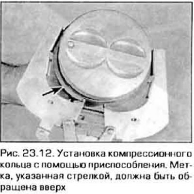
12. To install the second ring, it is better to use the device. Make sure the ring is facing up and insert it into the middle groove (pic. 23.12). Do not spread the ring more than necessary to pass through the piston.
13. Install the top ring in the same way. Remember that the marking must be facing up. Don't mix up the rings.
14. Similarly establish rings on other pistons.