
MazBook.ru
English Русский
Български
Беларускі
Український
Српски
Hrvatski
Română
Polski
Slovenský
Magyar
• Bookmark • Sitemap • Contacts •   
Cars Opel Cars Ford Cars Volkswagen Cars Audi Cars Kia Cars Renault Cars Peugeot


Familia Capella Mazda3 Mazda6 CX-? Others Articles
Capella 3 (1982-1992, petrol) Capella 3 and 4 (1982-1992) Capella 4 (1987-1992) Capella 5 (1991-1997) Capella 6 (1997-2005, petrol)

Cylinder block — inspection (Mazda Capella GF)

  • Home
  • Mazda Capella
  • Capella GF (1997-2005)
  • Power unit
  • Engine overhaul
  • Cylinder block — inspection
0
1. Before inspecting the unit, it should be cleaned as indicated in paragraph 15.

2. Inspect the block for cracks and corrosion. Check the condition of the threads in the threaded holes. It is a good idea to check the block for hidden cracks, especially if it has been overheated during operation or if internal coolant leaks have been observed. This type of work can be carried out by some workshops and service stations that have the necessary equipment. If defects are detected, they must be corrected, if possible, or the unit must be replaced.

3. Inspect the inner surfaces of the cylinders for scratches and burrs.

4. Measure the taper and ovality of the cylinders as follows: (figure 16.4, a-c).
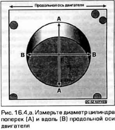
4. Measure the taper and ovality of the cylinders as follows: (figure 16.4, a-c).
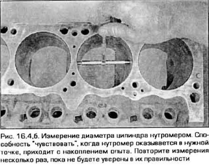

4. Measure the taper and ovality of the cylinders as follows: (figure 16.4, a-c).
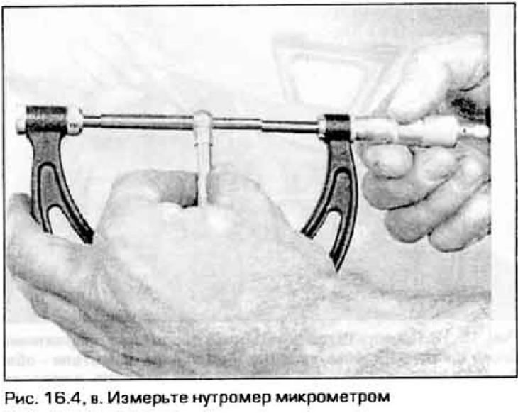

4. Measure the taper and ovality of the cylinders as follows: (figure 16.4, a-c).


5. Measure the diameter of each cylinder at the top (under the protruding flange), in the middle and at the bottom of the piston stroke in a direction parallel to the longitudinal axis of the engine. Then repeat the measurements at the same levels perpendicular to the engine axis.


6. The taper of each cylinder can be found as the difference in diameters at the top and bottom points of the cylinder. Ellipticity is the difference between the diameter measurements along and across the engine axis at the same level. Compare the obtained values with Technical data.

7. If Basne! doesn't have a special tool for measuring clearances between pistons and cylinders, these clearances can be measured using regular flat feeler gauges, although with less accuracy. Select a feeler gauge of the required thickness and insert it into the cylinder along with the corresponding piston. The piston should be positioned in the cylinder in the same way as during normal operation. The feeler gauge must be inserted along one of the side walls of the cylinder, located at a right angle to the longitudinal axis of the engine.

8. The piston together with the feeler gauge should move along the cylinder with some uniform friction.

9. If the piston easily falls into the cylinder, then the clearance is large and the piston needs to be replaced. If the piston passes the bore easily but gets stuck at the bottom, then the cylinder is taper. If you feel variable resistance when turning the piston in the cylinder, it means that the cylinder is elliptic.

10. Check the remaining cylinders in the same way.

11. If the cylinder bores have deep scratches or burrs, or if their taper or ellipse exceeds the permissible limits, send the block to a workshop for cylinder boring and honing. After boring the cylinders, pistons and rings of repair sizes should be used.


12. Using a steel ruler placed on its edge and feeler gauges, check the flatness of the mating surface of the block with the cylinder head (figure 16.12). If the flatness exceeds the permissible level, the surface can be corrected by mechanical processing on a machine.

12. Using a steel ruler placed on its edge and feeler gauges, check the flatness of the mating…


13. If the cylinder mirrors are in good condition and their dimensions are within tolerances, then boring of the cylinders is not required; honing is sufficient (see paragraph 17).

14. The design of all engines described in this Manual (both in-line and V-shaped), piston cooling is provided. For this purpose, special oil nozzles are installed in the cylinders. On a V-engine they are located at the bases of the main bearings in the upper block. They can be unscrewed and screwed in with a screwdriver. Unscrew, clean these injectors and screw them back into place with a thread seal. On a 4-cylinder in-line engine, the injectors are installed at the bottom of the cylinder bores. Their nozzles are directed towards the inner surface of the piston bottom. To remove and install these injectors, you need a special branded tool.

15. On the upper surfaces of both blocks of the V-shaped engine there are control plugs for the lubrication system (one on each block). The plugs can be pulled out with a self-tightening wrench and then new ones can be installed, replacing the sealing rings underneath. Hammer the new plugs into place with a mallet. The plugs should only be replaced after the block has been cleaned externally to prevent dirt from entering the oil system.

Note: Hammer the plugs in so that they protrude 13-14 mm above the block surface.
This article is available at: russian, bulgarian, belarusian, ukrainian, serbian, croatian, romanian, polish, slovak, hungarian
This text was checked by: German Vorobyov
Share with friends on social networks:

Previous
Capella 6 » Engine overhaul
Next

Cylinder block — cleaning
Crankshaft — removal
Pistons and connecting rods — removal
Cylinder head assembly
Valve maintenance
Cylinder honing
Pistons and connecting rods — inspection
Crankshaft — inspection
Main and connecting rod bearings — inspection and selection of liners
Camshafts and tappets — inspection
More articles on repairing other Mazda models
Technical characteristics of the cylinder block Mazda Familia 5 (1985-1989)
Cylinder Block — Description Mazda3 BK (2003-2009)
Cylinder block Mazda6 GG (2002-2008)
Assembly of the cylinder block and connecting rod and piston group Mazda CX-5KE (2012-2017)
Cylinder block Mazda BT-50 (1) (2006-2011)
Link in different formats to this article
Comments and feedback from visitors
No comments yet


How much will 45 + 50 ?


Capella 6 (1997-2005, petrol) 
  • General information
  • Introduction to guide
  • User manual
  • Troubleshooting
  • Maintenance
  • Power unit
  • 4-cylinder engines
  • 6-cylinder engines
  • Engine overhaul
  • Cooling and ventilation
  • Power and exhaust systems
  • Engine electrics
  • Control system
  • Transmission
  • Mechanical gearbox
  • Automatic gearbox
  • Clutch and drive shafts
  • Chassis
  • Brake system
  • Car suspension
  • Steering
  • Body
  • Exterior (external elements)
  • Interior (internal elements)
  • Doors, windows and locks
  • Electrical equipment
  • Equipment and devices
  • Electrical circuits
Capella 5 (1991-1997) 
  • General information
  • User manual
  • Maintenance
  • Helpful hints
  • Power unit
  • Petrol engines 1.6 and 1.8
  • Petrol engines 2.0
  • 2.5 petrol engines
  • Overhaul engines 1.6 and 1.8
  • Overhaul engines 2.0 and 2.5
  • Diesel engine 2.0
  • Engine electrics
  • Cooling system
  • Air conditioner
  • Carburetor Nikki 30/34
  • Power system (1.6 and 1.8)
  • Power system (2.0 and 2.5)
  • Control system
  • Transmission
  • Mechanical gearbox
  • Automatic gearbox
  • Clutch and axles
  • Chassis
  • Brake system
  • Suspension and wheels
  • Steering
  • Body
  • Exterior (external elements)
  • Interior (internal elements)
  • Doors and windows
  • Electrical equipment
  • Equipment and devices
  • Electrical circuits
Capella 4 (1987-1992) 
  • General information
  • Introduction to manual
  • Vehicle specifications
  • Power unit
  • Engine repair
  • Lubrication system
  • Cooling system
  • Fuel system (carburetor)
  • Fuel injection (FE)
  • Fuel injection (DOHC)
  • Fuel system (diesel)
  • Ignition system
  • Transmission
  • Clutch
  • Gearbox
  • Drive shafts
  • Chassis
  • Front suspension
  • Rear suspension
  • Steering system
  • Brake system
  • Electrical equipment
  • Equipment and devices
  • Electrical circuits
Capella 3 and 4 (1982-1992) 
  • General information
  • User manual
  • Maintenance
  • Power unit
  • Gasoline engine
  • Engine overhaul (gasoline)
  • Diesel engine
  • Cooling and heating
  • Supply system
  • Ignition system
  • Emission reduction
  • Transmission
  • Clutch
  • Mechanical gearbox
  • Automatic gearbox
  • Drive shafts
  • Chassis
  • Brake system
  • Suspension and wheels
  • Steering
  • Body
  • Exterior (external elements)
  • Interior (internal elements)
  • Electrical equipment
  • Equipment and devices
  • Power devices
  • Electrical circuits
Capella 3 (1982-1992, petrol) 
  • General information
  • User manual
  • Maintenance
  • Troubleshooting
  • Late models
  • Power unit
  • Engine in car
  • Engine overhaul
  • Cooling and heating system
  • Fuel and exhaust system
  • Engine electrical system
  • Emission control system
  • Transmission
  • Mechanical gearbox
  • Automatic gearbox
  • Clutch and drive shafts
  • Chassis
  • Brake system
  • Suspension and wheels
  • Steering
  • Body
  • Exterior (external elements)
  • Interior (internal elements)
  • Electrical equipment
  • Equipment and devices
  • Lighting and lamps
  • Electrical circuits
MazBook.ru © 2018–2026 · Mobile version · Articles and news · Sitemap: EN BG BY UA RS HR RO PL SK HU · Feedback · Site search · Add to bookmarks Familia 5 (BF) · Familia 6 (BG) · Capella 3 (GC) · Capella 3 and 4 (GC) · Capella 4 (GD) · Capella 5 (GE) · Capella 6 (GF) · Mazda3 BK · Mazda6 GG · CX-5KE · Mazda 121 (3) · Mazda BT-50 (1) ·
By continuing to use the site, you agree to the use of cookies 🔐