
2. Inspect the main and connecting rod journals for uneven wear, cracks, nicks, scratches, and pitting.
3. Remove burrs from the edges of the oil holes with a needle file or scraper.
4. Inspect the remaining surfaces of the shafts for cracks or other damage. It's a good idea to check the shaft with magnoflox for internal cracks - this can be done in a specialized workshop.
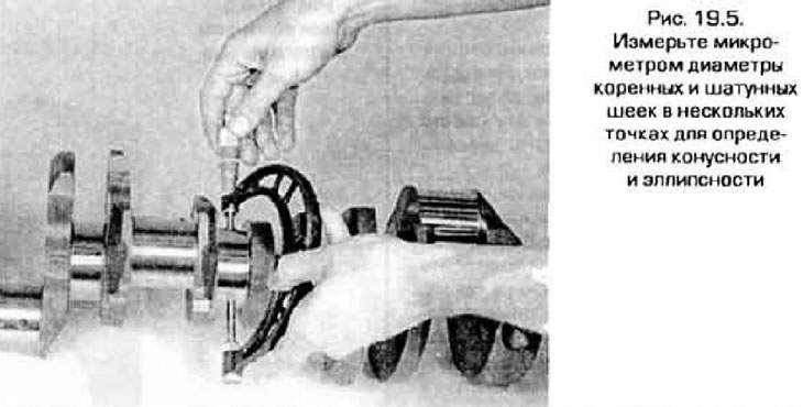
5. Measure the diameters of the main and connecting rod journals with a micrometer and compare the results with technical data (see fig. 19.5). By measuring the diameter of the neck in several wheelbarrows around the circumference, determine the ellipse. To determine the taper, measure the diameter at both ends of the necks and near the cheeks. You should also check the runout of the shaft, but this requires, in addition to the dial indicator, a large instrumental prism. If you do not have such a tool, contact a suitable workshop.
6. If wear, ovality, or taper is out of tolerance, send the shaft for regrooving. After that, when installing the led, use the repair size liners.
7. Inspect the seal surfaces at both ends of the shaft for excessive wear and damage. If the cuff has worn a groove in the neck, the new cuff will leak. In some cases, the workshop can correct this defect by turning the neck and pressing a thin sleeve onto it. If such a repair is not possible, the shaft will have to be replaced.
8. Measure the length of the main bearing cap bolts from the underside of the head to the end of the thread. On 4-cylinder engines, the bolt length should not exceed 68.5 mm, and on V-engines - 138.5 mm for long bolts and 121.0 mm for short ones. If the length of the bolts exceeds the specified values, then the bolts have stretched during operation and must be replaced. If at least one bolt is found to be defective, replace the entire set of bolts.
9. Inspect the main and connecting rod bearing shells as indicated in paragraph 20.