
Note. If the engine has been subjected to severe overheating, it may turn out that the cylinder head is warped (see ch. 12).
Cleaning
2. Scrape off any old gasket and sealant from surfaces mating with block and manifolds. Be careful not to scratch the surfaces. A special solvent is commercially available for removing gasket residue, which softens their material and greatly simplifies the operation
3. Remove deposits from all channels of the cooling system.
4. Clean all openings with a metal brush to remove deposits and rust.
5. Drive all threaded holes with a cooieeiciByiOLuero size tap to clean the threads of dirt and rust. If possible, blow out the holes with compressed air.
Attention! Protect your eyes when working with compressed air.
6. Clean the connector studs with a metal brush.
7. Wash the head with solvent and dry thoroughly. Compressed air will speed up the drying process and increase the likelihood that no debris will remain in the channels of the head.
Note. Suitable chemicals are commercially available for removing carbon deposits from the combustion chamber and valves. These are highly caustic substances and must be handled with care. Strictly follow the manufacturer's recommendations.
8. Wash with solvent and dry the pushers. Compressed air will speed up the drying process and remove any remaining oil from the holes. When flushing, do not mix up the tappets - store them together with the corresponding valves. Hydraulic tappets should be stored in a container with oil "upside down".
9. Rinse and dry valve springs, plates and crackers. Work in turn with each set of parts so as not to mix them up later.
10. Scrape off carbon deposits from the valve heads, then clean the valve heads and stems with a wire brush in the drill.
Inspection
Note Before. Before making a decision about the need to machine the head i, perform all the check operations indicated below. The procedure for checking hydraulic tappets is described in paragraph 27.
Cylinder head
11. Inspect the head very carefully for cracks, obvious signs of coolant leaks and other damage. If there is a third, consult a service station about the possibility of repair and, if repair is not possible, replace the head with a new one.
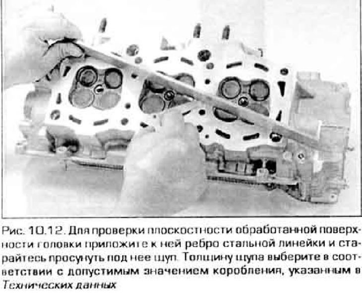
12. Using a steel ruler placed on the ribs and a set of flat feelers, check the mating planes of the head (OK) for warping (pic. 10.12). If warpage exceeds the allowable level, the head can be corrected by machining in the workshop.
13. Inspect the valve seats in all combustion chambers. If they have pitting, burns or cracks. give the head for repair to specialists - it is not recommended to do this work on your own.
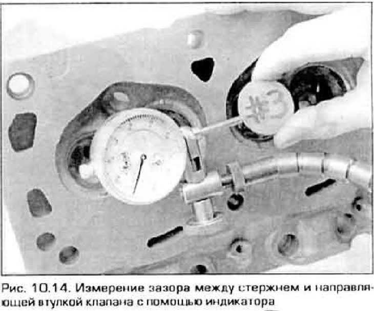
14. Check up a backlash between cores and directing plugs of valves. For this purpose, you can use a caliper and a micrometer or dial indicator (pic. 10.14). When checking with an indicator, the valve should be in the guide sleeve, and its plate should not reach the seat by 15 mm. Mix the whole rod between the walls of the guide bush (shaking the rod will give the wrong result) and read the indicator. If the gap exceeds the allowable value specified in Technical Data guide bushing must be replaced.
Valves
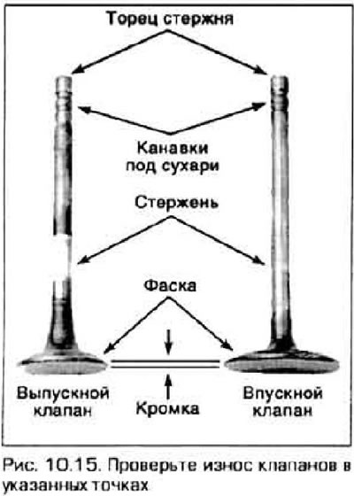
15. Carefully inspect the valve discs for excessive wear, deformation. shells, cracks and burns (pic. 10.15). Inspect the valve stem for nicks and wear, and the stem neck for cracks. Rotate the clans for signs of curvature. Look for excessive wear on the end of the rod. If any of these signs are found, the valve must be machined or replaced.
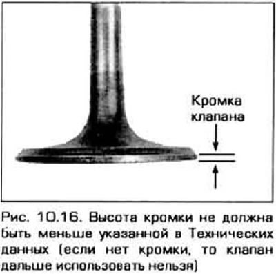
16. Measure the height of the edge of the valve disc (pic. 10.16). If the edge height is less than the allowed (see technical data), the valve needs to be replaced.
Valve train parts
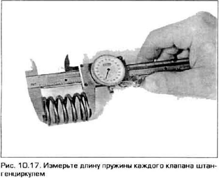
17. Inspect the ends of the springs for pitting and wear. Measure the free height of the springs (pic. 10.17) and compare the results with technical data. All springs shorter than the specified length must be replaced. It is also desirable to remove the characteristics of the springs, i.e. dependence of displacement on load. Typically, the home workshop does not have equipment for such a check, so they should be taken to a service station.
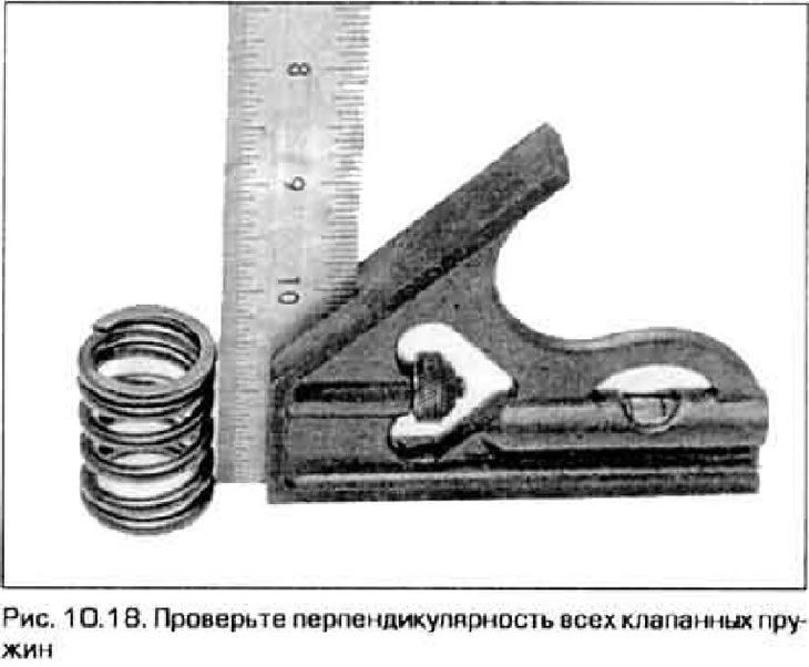
18. Put the spring on a flat base and check its perpendicularity (pic. 10.18). If any of the springs is bent or out of square, replace the entire set of springs.
19. Examine plates of springs and crackers on presence of obvious deterioration and cracks. All suspicious parts should be replaced with new ones, as their failure while the engine is running can cause very serious malfunctions.
20. All worn or damaged parts of the valve group must be replaced.
21. If all valve parts are in poor condition, which is common for an engine requiring overhaul, replace the entire valve group and install new valves as recommended paragraph 11.