
Note. Before removing the connecting rod and piston groups, remove the cylinder head, sump, oil intake pipe and oil damper, as described in chapter 2A or 2B.
1. On a 4-cylinder engine (only) remove the amplifier block by unscrewing the bolts of its fastening in the opposite order to that indicated above (see figure 13.23 chapter 2A).
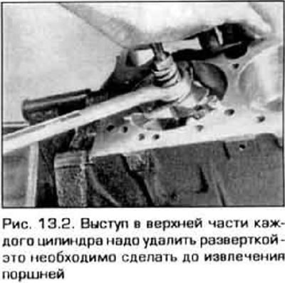
2. Run your finger inside the top end of the cylinder mirror to feel. pi did not form a ledge on it from wear by piston rings (about 6 mm from the end of the cylinder). When a ledge is formed, it is necessary to remove the protruding edge of the cylinder with a special tool (pic. 13.2). Follow the instrument manufacturer's instructions. If the protrusion is not removed, the piston may be damaged during removal.
3. After removing the protrusions in the cylinders, turn the engine upside down with the crankshaft.
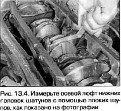
4. Before dismantling the lower head of the connecting rod, check its end play. Slide the head all the way into the crankshaft web and measure the clearance between the head and the second web with a set of feeler gauges (pic. 13.4). If the axial play exceeds the value specified in Technical Data, the connecting rod needs to be replaced. When installing a new connecting rod or when replacing the crankshaft, the end play of the connecting rod may be below its minimum limit. In this case, the connecting rod can be reworked (consult on this issue at the service station). Check up in the same way other rods.
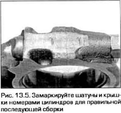
5. Check up, there are pi tags on rods and covers. If such marks could not be found, number them according to the cylinder numbers yourself with a center punch or digital stamps (pic. 13.5).
6. Loosen the connecting rod cap nuts 1/2 turn at a time until they can be removed by hand. Remove the cover of the first connecting rod in place with the liner - do not let the liner fall out of the cover.
7. Remove the bearing shell and push the connecting rod with the piston out of the block and over the top of the engine. To do this, press the wooden handle of the hammer on the bearing surface of the connecting rod. If resistance is felt when pushing out, check again that the protruding shoulder at the top of the cylinder is well removed.
8. Remove the other pistons in the same way.
Note. Rotate the crankshaft as necessary so that the connecting rod of the piston to be removed is located approximately along the axis of the cylinder, then do not try to remove the piston if the connecting rod is located at a large angle to the generatrix of the cylinder.
9. After removing the pistons, reassemble the lower heads of the connecting rods with liners so that all parts of the connecting rod bearings are in their original places. Secure the head covers with nuts by hand. Keeping the bearings in place until the engine is reassembled will prevent accidental damage to the connecting rod bearing surfaces.
10. Do not disconnect pistons from connecting rods (see paragraph 18 for details).