


Contents: Removal ⇓ Installation ⇓
Note: Please read the entire paragraph before proceeding. The manufacturer recommends removing the entire powertrain assembly through the top of the engine compartment and then separating the transmission from the engine on the floor. This is true for all V-engine models, as well as for 4-cylinder models with manual transmission. On models with a 4-cylinder engine and automatic transmission, the engine can be removed while leaving the transmission in the vehicle (propping it up with a jack).
Removal
Please note: All vehicle models described in this manual are equipped with an airbag. The airbag is armed and can deploy at any time if there is voltage in the on-board network. To prevent accidental deployment of the airbag (and possible injury from atomic force), whenever you have to work near the airbag, turn the ignition key to the off position and disconnect the negative battery terminal. After disconnecting the battery, wait at least two minutes before continuing work (the security system is equipped with a backup power source - a capacitor, which must have time to discharge). For more information, see. v chapter 12.
Caution: Gasoline is highly flammable, so use extreme caution when working anywhere in the fuel system. Do not smoke in the work area, do not use an open flame or an unprotected portable lamp. If there are gas appliances with a pilot light in the garage (like water heaters and dryers), turn them off. Gasoline is also a carcinogen. For this reason, protect your hands with plastic gloves when handling fuel. Clean up any spilled gasoline immediately and wash off any traces with soap and water. Do not store rags soaked in gasoline in places where they may ignite. The fuel system is always under positive pressure, so before disconnecting the fuel line, relieve the pressure in it (see chapter 4). Keep a carbon dioxide fire extinguisher handy and familiarize yourself with the rules for using it in advance.
1. Relieve the pressure in the fuel system (see chapter 4).
2. Disconnect the negative cable from the battery.
Caution: If your vehicle's audio system is equipped with an anti-theft device, make sure you have the unlock code before disconnecting the battery.
3. Remove the battery and its tray.
4. Cover the front fenders of the car with pieces of cloth to protect the paint, Remove the hood (see chapter 11).
5. Remove the air cleaner (see chapter 4). Remove the splash guard from under the engine.
6. Raise the vehicle and secure it on stands. Drain the coolant, oil from the engine and remove the drive belts (see chapter 1).
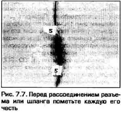
7. Label and disconnect all water and vacuum hoses, electrical connectors. grounding buses and fuel lines. For marking, you can use quick-drying nitro paint or pieces of adhesive tape (figure 7.7). It would be a good idea to take a photo or sketch the location of hoses, wires, brackets, etc. beforehand.
8. Remove the cooling system fan and radiator (see chapter 3). Remove the upper and lower radiator hoses. Disconnect the heater hoses from the engine.
9. Release any residual pressure in the fuel system by unscrewing the tank cap, then disconnect the fuel pipes connecting the engine to the chassis (see chapter 4). Plug or close all connection openings.
10. On a 4-cylinder engine, remove the intake manifold support bracket.
11. Remove the starter (see chapter 5).
12. Remove the crankshaft pulley (see chapters 2A or 2B).
13. On a 4-cylinder engine, remove the generator (see chapter 5).
14. Disconnect the throttle actuator and speed control cable from the engine (if there is one).
15. Disconnect the engine wiring connectors and unhook the wiring harnesses (figure 7 15.a-c). Move the wiring away from the engine.
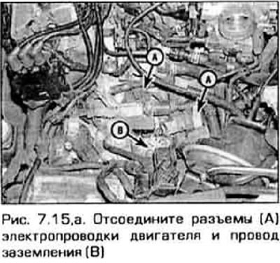
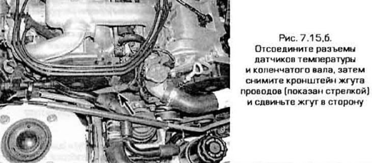
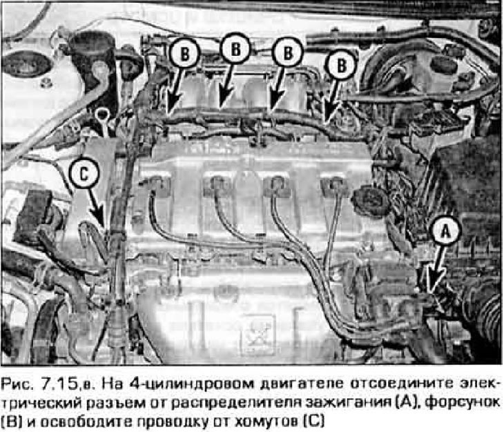
16. On vehicles equipped with power steering, remove the power steering pump. If space allows, mount the pump somewhere on the side without disconnecting its hoses. If necessary, remove the pump completely (see chapter 10).
17. On models with air conditioning, remove the compressor mounting bolts and secure it to the side. Do not disconnect the refrigerant hoses.
18. Disconnect the electrical connector from the oxygen sensor. Disconnect the exhaust system inlet pipe and manifolds (see chapter 4). Remove the crossmember and lower the receiving pipe.
19. On a V-shaped engine with an oil heat exchanger, unscrew the oil filter, disconnect the cooling system hoses and remove the heat exchanger (see chapter 3).
20. Attach the slings to the engine rigging eyes (figure 7.20). Set up the lift and attach the slings to it. Take up the slack and tighten the slings slightly.
(The text of the article is taken from the website: «Mazbook.ru»)
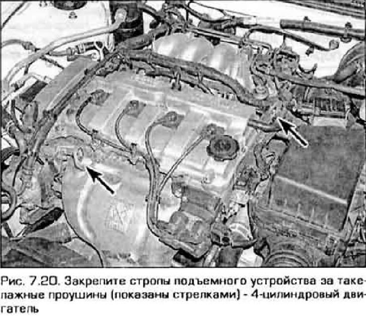
21. On a model with a 4-cylinder engine and automatic transmission, remove the drive shaft from the passenger side (see chapter 8). Remove the lower transmission housing cover under the torque converter. Release the torque converter from the faceplate (see chapter 7) and push the torque converter into the transmission housing.
22. On all models with a V-shaped engine and on models with a 4-cylinder engine and manual transmission, the power unit is removed from the vehicle as an assembly. Disconnect all drives and electrical connectors from the transmission (see chapter 7). Remove both drive shafts (see chapter 8).
23. Loosen the bolts/nuts securing the front and rear power unit supports to the chassis and the lower support to the subframe (see chapters 2A or 2B).
24. On a model with a 4-cylinder engine and automatic transmission, remove the bolts connecting the transmission to the engine and move the transmission away from the engine. The torque converter must remain in the transmission. Support the transmission with a jack, placing a wooden block on its head to avoid damaging the transmission housing. On other models, the transmission is removed together with the engine and the bolts that secure the transmission to the engine are not yet unscrewed.
25. Make sure once again that. that nothing but the right and left supports connects the engine to the car.
26. Remove the bolts of the right and left supports. Caution: Do not place your hands under the power unit while it is supported only by the lifting device.
27. Slowly lift the power unit out of the engine compartment. It may be necessary to lever the supports out of the brackets.
28. Move the power unit behind the car's i-peneriu and carefully lower it onto the pop or remove the flywheel (faceplate) and install the engine on the stand.
Note: On models with automatic transmission, label the faceplate adapters and store them with the faceplate.
Installation
29. Check the condition of the power unit supports. If they are worn or damaged, replace them.
30. On a model equipped with a manual transmission, check the clutch components (see chapter 8). On models with automatic transmission, check the condition of the seal and bearings of the torque converter.
31. On a model with a manual transmission, lubricate the clutch release bearing with grease. On models with automatic transmission, lubricate the nose of the torque converter with grease.
32. Carefully connect the transmission to the engine as described in chapter 7.
Warning. Do not attempt to force the transmission toward the engine by tightening the bolts. This may result in serious damage to expensive body parts.
33. Install the transmission to engine mounting bolts and tighten them securely.
34. Connect the lift to the power unit and carefully lower the unit into the engine compartment.
Note: If the engine was removed without the transmission and the transmission remains in the vehicle, lower the engine into the engine bay and have an assistant align the transmission with the engine. This will require slightly rotating the engine or transmission. The combination of the torque converter with the faceplate is described in Chapter 7.
35. Screw in the support bolts and tighten them securely.
36. Install the remaining parts and components in the reverse order of removal.
37. Fill the coolant, engine oil, transmission fluid and power steering fluid (see chapter 1).
38. Start the engine and make sure it is working properly and there are no leaks. Turn off the engine and check the fluid levels again.