


Note. The crankshaft can only be removed if the engine is removed from the vehicle. It is assumed that by the time the crankshaft is removed, the flywheel has already been removed (or faceplate), crankshaft pulley and sprocket, sump, oil pump, oil pipe and pistons with connecting rods. Before continuing with disassembly, remove the rear cuff with the clip.
1. Before removing the crankshaft, check its end play. To do this, fix the dial indicator so that the measuring rod is directed along the axis of the shaft, and its tip touches the end of the shaft (pic. 14.1).
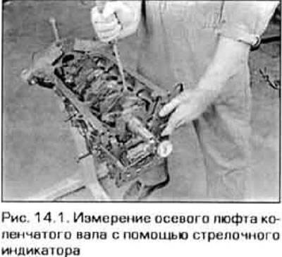
2. Move the shaft back as far as it will go and set the indicator scale to zero. Now, using the lever, move the shaft forward until it stops and read the value of the axial play on the indicator. If this value exceeds the allowable level specified in Technical Data, check the thrust surfaces of the crankshaft for wear. If wear is not noticeable, replacing the thrust bearings will help eliminate excessive play.
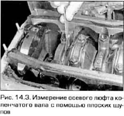
3. In the absence of a dial indicator, you can use a set of flat probes. Move the crankshaft by hand or lever to the front of the engine. Measure the clearance between the thrust bearing of the 4th main bearing and the thrust surface of the crankshaft (pic. 14.3). The thrust bearing on all engines is located on the fourth main bearing. There are only five main bearings on a 4-cylinder engine, and four on a V-shaped engine.
4. On a 4-cylinder engine, make sure the main bearing caps are marked with the bearing number from first cylinder to last. If there is no marking, apply it yourself using digital stamps or a center punch. The covers usually have an arrow pointing towards the front of the engine. Gradually loosen the bolts securing the support covers, turning them off no more than a quarter of a turn at a time, in sequence, the reverse of the tightening sequence (see fig. 24.12, a), until they can be pulled back by hand. On a V-shaped engine, unscrew the bolts securing the crankcase to the upper block in the sequence shown in fig. 14.4 until they can be unscrewed by hand.
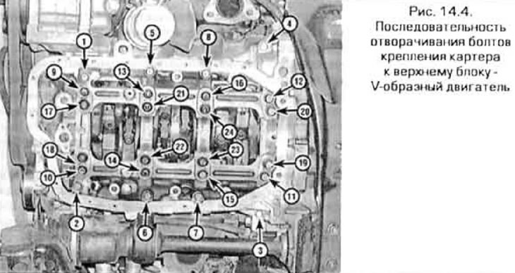
Note. On a V-shaped engine, the covers of the main bearings of the crankshaft are made integral with the crankcase. In order to remove the crankshaft, the crankcase must be disconnected from the upper block. Note the position of all crankcase bolts as there are three sizes.
5. Tap the bearing caps or crankcase lightly with a soft-faced hammer, then remove them from the shaft. Take care not to drop the earbuds if they remain inside the caps.
6. Gently lift the crankshaft. In this case, it is better to use someone else's help, since the shaft is quite heavy. Insert the bushings into the old places in the supports and covers and screw the bolts by hand.