
2. Install the block with the main bearings facing up.
3. Remove the bolts and remove the main bearing caps or lower crankcase (V6 engines): Arrange the covers in the order in which they were installed.
4. If the old earbuds are still in place, remove them. Wipe the surfaces under the earbuds in the unit and in the covers with a clean, lint-free cloth. Surfaces must be sterile clean!
Checking clearances in main bearings
5. Wipe the outer surfaces of the new liners and lay the liners with oil holes in the bed of the block. Put the second halves of the sets into the covers of the corresponding supports or into the lower crankcase (V6 engines). Then make sure that the protrusion of each earbud falls into the cutout intended for it. In addition, the oil holes in the block supports and in the liners must match.
Attention! Do not drive the liner into place if it does not fit there. Do not rumple or scratch the surface of the earbuds. Do not use any lubricant at this stage.
6. On all engines, thrust bearings are installed in support No. 4, counting from the toothed belt
7. Wipe the inside surfaces of the bearings in the block and the crankshaft journals with a clean, lint-free cloth. Check for dirt in the oil holes of the crankshaft and clean them if necessary, because the dirt will immediately get on the surfaces of the new liners.
8. Carefully lower the crankshaft into the supports.
9. Before the final installation of the shaft, it is necessary to check the clearances in the main bearings.
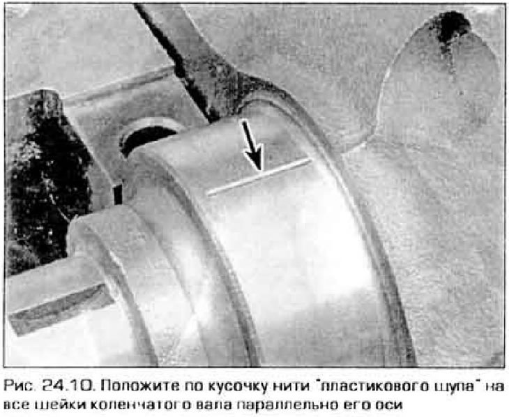
10. Cut off a few pieces "plastic probe" (they should be slightly shorter than the width of the earbuds) and place them one by one on each main journal along the axis of the shaft (pic. 24.10).
11. Wipe the surfaces of the liners in the support covers and install the covers in their places with the arrow forward. On the V6 model, place the lower crankcase on the crankshaft. Don't budge "plastic probes". Lubricate the threads and undersurfaces of the heads of the cover bolts and insert the bolts into place.
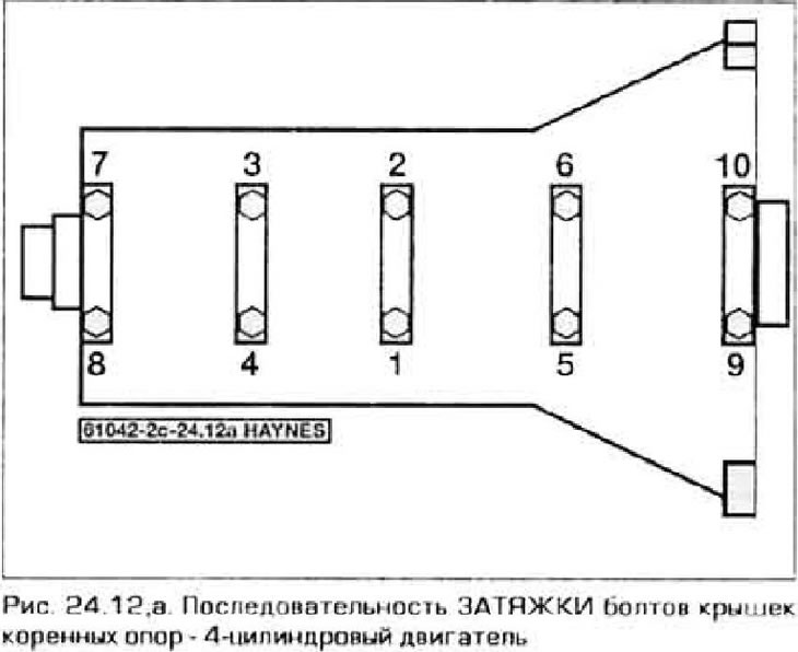
12. Tighten the bolts in the sequence shown in fig. 24.12, and in three stages until the tightening force specified in Technical Data this chapter. Rotate the crankshaft during this operation!
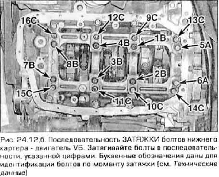
Note. On Vb engines, the lower crankcase mounting bolts are marked on the heads. bolts "A" (pic. 24.12, b) are marked "4", bolts "IN" marking "1", and the bolts "WITH" do not have any markings. After tightening the 16 bolts holding the crankshaft, tighten the bolts around the perimeter of the crankcase from its middle to the edges.
13. Turn away bolts and accurately remove covers or the lower case. Place the covers against the appropriate supports. Do not move the plastic or rotate the crankshaft. If a cover does not come off by hand, tap it gently on the side with a soft-faced hammer.
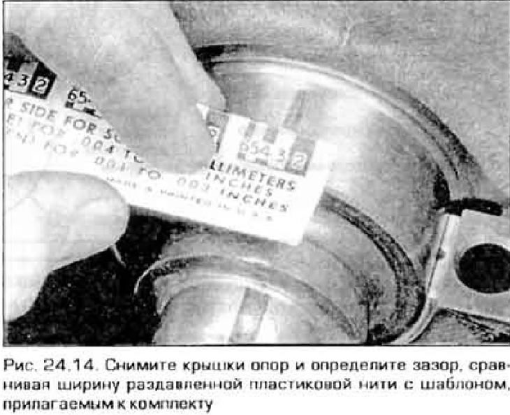
14. Compare the width of the flattened plastic bar with the template and read the gap from it (pic. 24.14). Compare the obtained values with technical data.
15. Inconsistency with the recommended gap may mean that the liners are the wrong size (in this case they need to be changed). Before making a decision to replace the liners, make sure that no dirt or oil has entered between the liners and the bores in the block or bearing caps during the measurement. If "plastic probe" noticeably wider on one side than on the other, this means that the shaft journal has a taper (see paragraph 19).
16. Carefully remove the remaining plastic from the necks or from the liners. Do not scratch the bearing surfaces.
Final installation of the crankshaft
17. Carefully remove the crankshaft from the supports. Wipe the surfaces of the liners in the block and lubricate them with a thin layer of molybdenum grease or special engine assembly grease. Lubricate the working surfaces of the thrust bearings as well (Don't forget to install them).
18. Lubricate the crankshaft journals under the cuffs with clean engine oil.
19. Wipe the shaft journals again and place it in the bearings. Wipe and lubricate the bearing surfaces in the covers or in the lower crankcase.
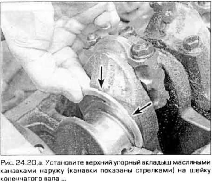
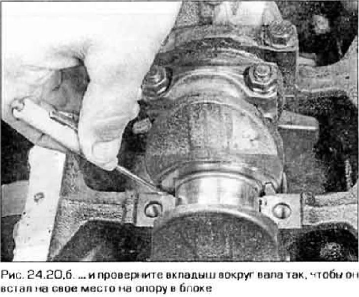
20. Upper thrust pads (block side) can be placed in working position. turning them relative to the installed crankshaft (rice 24.20, a, b). Insert the bushings into the fourth bearing, aligning them with the lubrication grooves away from the bearing. The upper liners must be installed in the support covers (or in the lower crankcase) grooves OUTSIDE and align the mounting tabs with the corresponding cutouts in the covers.
21. On a 4-cylinder engine, install the main bearing caps in their original places with the arrow forward. Lubricate the threads and bases of the bolt heads and insert them into place. Tighten the bolts in the recommended sequence (see fig. 24.12, a) in a number of ways as described in Technical Data.
22. On a V6 engine, apply a bead of RTV sealant to the surface of the lower crankcase that mates with the upper block. Reinstall the lower crankcase. Lubricate the threads and bases of the heads of the crankcase-to-block bolts, screw and tighten them in the sequence shown in fig. 24.12, b (see also point 12). The crankcase must be installed no later than 5 minutes after applying the sealant.
23. On models with a manual transmission, insert a guide bearing into the crankshaft shank (see chapter 8).
24. Turn the shaft several times by hand to make sure it is not pinched.
25. Check shaft end play using a dial gauge or feeler gauges (see paragraph 14).
26. Install a new rear seal and screw its body to the block (see paragraph 25).