


2. Remove the first connecting rod lower head cover (the connecting rods must be numbered). Remove the old bearings and wipe the bores of the small connecting rod head and its cap with a clean, lint-free cloth. Surfaces must be perfectly clean.
Checking the clearances in the lower connecting rod bearings
3. Wipe the outside of the upper connecting rod bearing and insert the connecting rod bore. Make sure that the bearing protrusion fits into the recess on the connecting rod and that the oil holes line up. Be careful not to scratch the working surface of the liner or drive the liner into the bore. Do not use oil at this stage.
4. Wipe the outer surface of the second half of the bearing and insert it into the connecting rod head cap. Align the tab on the insert with the cutout and, as before, do not lubricate anything. It is important that when assembling the connecting rod bearing, there is nothing extra between the bore of the lower head and the liners - no dirt or oil.
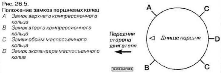
5. Rotate the piston rings so that their locks take the position shown in the figure 26.5.
6. Turn the engine on the stand with the crankshaft down.
7. Lubricate the rings and piston with engine oil and install a ring compression clamp on the piston. Leave 10-15 mm of skirt free to center the piston relative to the cylinder. The rings must be compressed so that they become flush with the piston surface.
8. Turn the crankshaft so that the crank of the first cylinder is in the BDC position. Lubricate the cylinder bore with engine oil.
9. Insert the piston so that its front mark faces the front of the engine and push the piston into the cylinder until the clamp stops against the block. On 4-cylinder engines, the front label "F" (front) is located in the recess next to the piston pin. On V-engines, in the same place there is a mark "A" for the right block and "I" for the left, which should also be turned towards the front of the engine during installation.
10. Tap the clamp until it fits snugly against the block surface all the way around.
11. Gently tap the piston niche with a wooden hammer handle (figure 26.11), push it down while simultaneously adjusting the lower connecting rod head so that it fits onto the crankpin of the crankshaft. The piston rings will try to jump out of the grooves as they pass from the clamp into the cylinder, so constantly press the clamp against the block, preventing the formation of a gap between them. Work slowly and if you experience any unusual resistance, stop immediately. Before continuing, find the cause of the increased resistance.
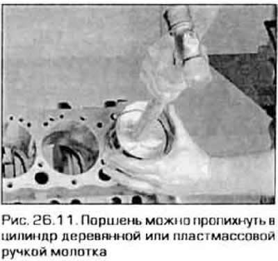
Caution! Under no circumstances should you attempt to force the piston forward. At best, you risk breaking the ring, and at worst, damaging the piston or cylinder.
12. Before finalizing the assembly of the small end of the connecting rod, the clearance in the connecting rod bearing should be measured.
13. Cut a piece of plastic rod of suitable length from the "plastic feeler gauge" kit and carefully place it on the crankpin along the shaft axis (figure 26.13).
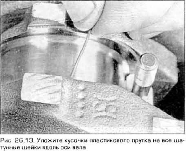
14. Wipe the inside surface of the bearing cap liner and reinstall the cap. Then make sure that the mark on the cover is on the same side as the mark on the connecting rod.
15. Lightly lubricate the undersides of the mounting nuts, thread them onto the bolts and tighten in three stages to the torque specified in Technical data this chapter. To ensure proper tightening, ensure that the socket head does not become pinched between the nut and the connecting rod cap. The gap here is quite small and you will need a thin wall socket. Do not turn the crankshaft during this operation.
16. Unscrew the nuts and remove the cover, being careful not to displace the plastic rod.
17. Compare the width of the flattened plastic rod with the template and read the gap value from it (figure 26.17). Compare the obtained value with Technical data.
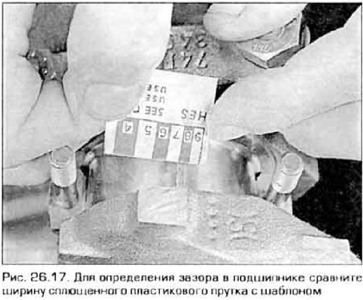
18. If the clearance does not match the recommended one, it may mean that the bearings are of the wrong size (in this case they need to be changed). Before deciding to replace the bearings, make sure that no dirt or oil has entered between the bearings and the bores in the connecting rods or bearing caps during measurement. If the "plastic feeler gauge" is noticeably wider on one side than the other, it means the crankpin is tapered (see paragraph 19).
Final installation of connecting rods
19. Carefully remove any remaining plastic from the necks or liners. Be careful not to scratch the bearing surfaces; scrape off the plastic with your fingernail or a credit card.
20. Make sure the bearing surfaces are completely clean, then lubricate them with molybdenum grease or engine assembly grease - you will have to push the piston into the cylinder a little to get to the surface of the upper bearing. To avoid scratching the crankshaft journal, place protective tubes on the connecting rod bolts.
21. After lubricating the liners, lower the lower head of the connecting rod back into place, remove the protective tubes from the bolts, install the cover in place and tighten it with nuts until the specified force is achieved Technical data.
22. Repeat this procedure with the remaining connecting rods.
23. It is important to remember the following:
- a) The surfaces of the liners and bores in the connecting rod and cover must be absolutely clean before assembly.
- b) Inserting the piston into the cylinder. You must be sure that you are inserting the correct piston.
- c) The mark on the piston must face the front of the engine.
- d) Lubricate the cylinder walls with clean oil only.
- d) Lubricate the bearing shells and shaft journals only during final assembly, after checking the clearances.
24. After all connecting rods are fully installed, turn the crankshaft by hand several times to ensure there is no binding.
25. The following operation was performed: checking the axial play of the lower head on the crank - see paragraph 13.
26.Compare the measured value of axial play with Technical data. If it was within acceptable limits before the overhaul, and if you did not change the connecting rods, it should remain the same. If the connecting rods or crankshaft were replaced, the play may have gone beyond acceptable limits. In this case, the connecting rods will have to be removed and sent to a workshop for mechanical reworking.