


Application: This procedure applies to both front and rear disc brakes.
Examination
1. Loosen the wheel nuts. raise the car and place it on supports. Remove the wheel and screw on the wheel nuts, placing 3 mm thick washers underneath them (they may be needed to press the disc to the hub). If the disk is secured with two screws, there is no need to tighten the nuts. When checking the rear disc, release the parking brake.
2. Remove the caliper (see paragraph 4), however, do not disconnect the hose from it. Move the support to the side and tie it with a piece of wire.
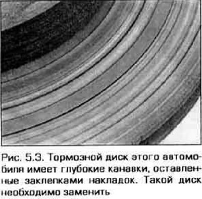
3. Inspect the brake disc surface and ensure there are no burrs or other damage (figure 5.3). Small scratches and shallow grooves always occur during vehicle operation and do not affect the efficiency of the braking system, however, if there are deep scratches (depth over 1.0 mm) the disc will need to be sanded. Inspect both sides of the disc.
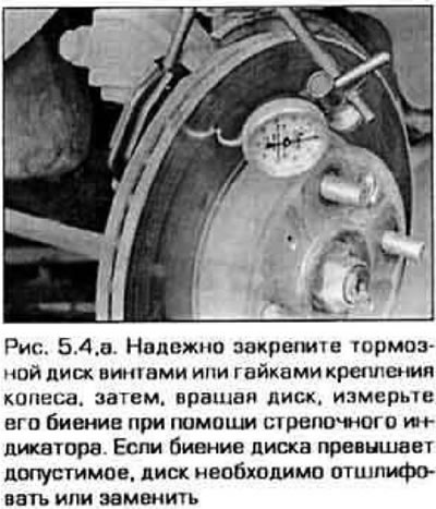
4. If the car slows down unevenly during smooth braking, the cause may be a beating brake disc. To check the disc runout, place the dial indicator approximately 15 mm from the outer edge of the disc (figure 5.4,a). Set the indicator scale to 0 and rotate the brake disc by hand. The indicator readings must not exceed the permissible runout value. If the disc runout exceeds the maximum allowable, grind the disc.
Note: Grinding the disc is beneficial even if the runout does not exceed the permissible value, since it eliminates uneven deceleration of the vehicle during braking. If you do not plan to sand the disc, remove shiny spots on its surface using circular movements of sandpaper (figure 5.4,b).
 |
 |
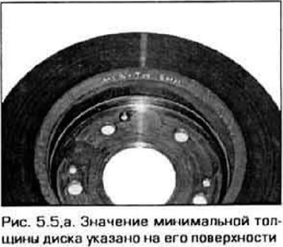
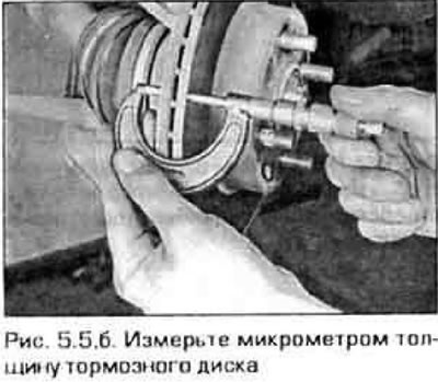
5. If the thickness of the disc is less than the minimum allowable, it cannot be ground. The minimum thickness of the disc is indicated on its non-working surface (figure 5.5,a). Measure the thickness of the disc with a micrometer (figure 5.5,b). Measure the thickness of the disc at several points.
 |
 |
Removal
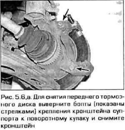
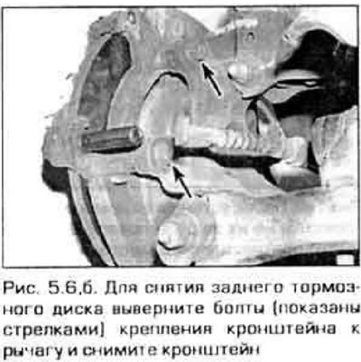
6. Remove the caliper (if it hasn't already been done), but do not disconnect the hose from it (see paragraph 4). Remove the two bolts securing the caliper bracket to the steering knuckle (figure 5.6,a) or, for the rear brake, the bracket-to-lever mounting bolts (figure 5.6,b).
 |
 |
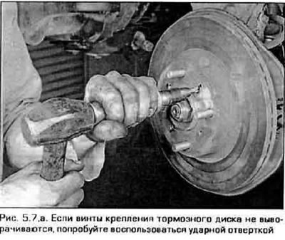
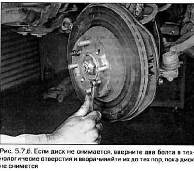
7. Loosen the wheel nuts (if they were used to fix the disc) or two brake disc mounting screws (figure 5.7,a) and remove the disc from the hub. If the disk does not come off, screw two bolts into the special holes (figure 5.7,b) and tighten them. By evenly screwing both bolts in, press the disc away from the hub.
 |
 |
(Based on website data www.MAZbook.ru)
Installation
8. Install the disc onto the wheel studs. Insert the drive mounting screws and tighten them securely.
9. Install the caliper bracket, pads and caliper. Tighten the bracket and caliper mounting bolts to the specified torque. If you are installing a rear disc, adjust the wheel cylinder piston (see paragraph 3).
10. Install the wheel and lower the vehicle. Press the brake pedal several times to ensure that the pads touch the disc. If you have not disconnected the hose from the wheel cylinder, there is no need to bleed the hydraulic system. Check the efficiency of the braking system before driving.