
Checking work
1. Press the brake pedal and start the engine. If the brake pedal falls slightly down, then the booster is working.
2. With the engine running, depress and release the brake pedal several times. Make sure the pedal travel does not change (the distance between the pressed ice in the lead and the floor remains unchanged).
Leak test
3. Start the engine and stop it after 1-2 minutes. Slowly press the brake pedal several times. If each time the brake pedal moves a shorter distance, then the booster is airtight.
4. Start the engine, depress and hold the brake pedal Stop the engine. If within 30 seconds the pedal travel does not change, then the amplifier is airtight.
Removing
5. Vacuum booster is non-separable. Equipment is required to repair it. which is not available at regular service stations. For these reasons, a defective brake booster must be replaced with a new or remanufactured one.
6. Remove the brake master cylinder (see paragraph 8).
7. Remove the hose connecting the vacuum booster to the engine. Be careful. so as not to damage the hose connection to the amplifier.
8. Find the pin of the pusher that connects the booster to the brake pedal.
9. Using pliers, remove the cotter pin, then remove the pin.
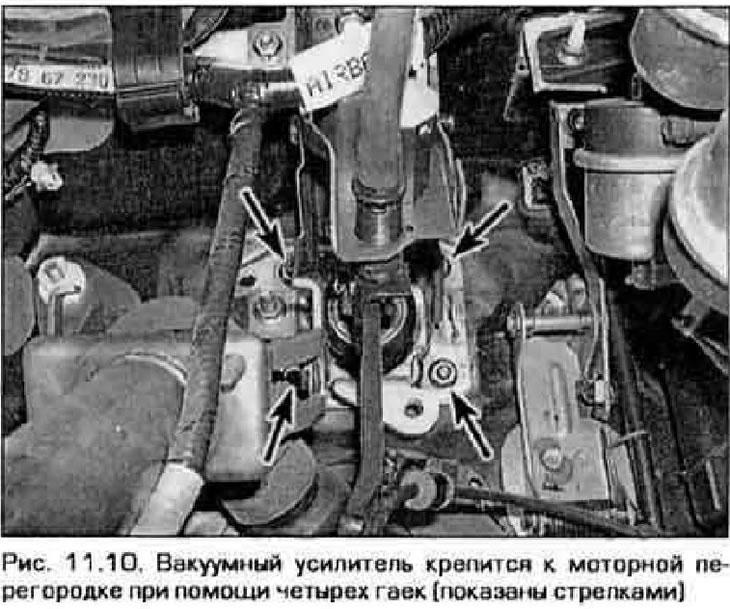
10. Turn away four nuts of fastening of the amplifier to a motor bulkhead (pic. 11.10). You will need a portable lamp for this job, as access to the nuts is difficult.
11. Remove the amplifier from the baffle, then turn it to the right (to the center of the engine) so that the pusher comes out of the bulkhead, then remove the amplifier from the engine compartment.
Installation
12. Installation is made in sequence, return to removal. Tighten the booster mounting nuts to the required torque. Also, install a new push pin.
13. When replacing the booster, you will need to adjust the clearance between the master cylinder piston and the pusher of the booster, which is done as follows.
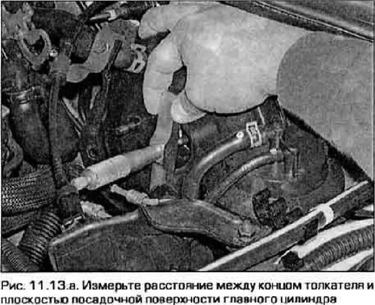
- A) Using a manual vacuum pump, create a vacuum in the amplifier booster equal to 500 mm Hg. Art. Measure the distance between the end of the pushrod and the plane of the seating surface of the master cylinder. Write down the measured number (pic. 11.13, a). This size is denoted by the letter "A".
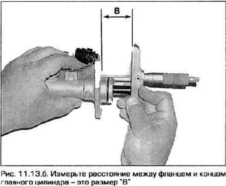
- b) Measure the distance between the master cylinder flange and its stroke (pic. 11.13.6). Write down the measured number. This size is denoted by the letter "IN".
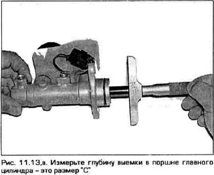
- V) Measure the recess depth of the master cylinder piston (pic. 11.13, in). Write down the resulting number. This size is denoted by the letter "WITH".
- G) Subtract the number "WITH" from "IN" then subtract the resulting number from the size "A". The resulting value is the gap between the piston of the main cylinder and the booster pusher.
- d) Compare the learned gap value with technical data. If necessary, adjust the length of the pusher so that the gap is within the allowable limits (see below). If "D" less difference "B-C", it is necessary to reduce the length of the pusher. If "A" more than "A-C" increase the length of the pusher to ensure the correct clearance.
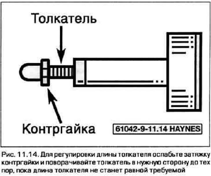
14. If the clearance needs to be adjusted, loosen the lock nut and turn the vacuum booster pusher until. until the required clearance is achieved (fig 11.14). Tighten the locknut after adjustment is complete. Re-measure the clearance. Repeat the adjustment procedure until the required clearance is obtained.
15. After installing the master cylinder, connect all the pipelines and bleed the brake system (see paragraph 10).