
MazBook.ru
English Русский
Български
Беларускі
Український
Српски
Hrvatski
Română
Polski
Slovenský
Magyar
• Bookmark • Sitemap • Contacts •   
Cars Opel Cars Ford Cars Volkswagen Cars Audi Cars Kia Cars Renault Cars Peugeot


Familia Capella Mazda3 Mazda6 CX-? Others Articles
Capella 3 (1982-1992, petrol) Capella 3 and 4 (1982-1992) Capella 4 (1987-1992) Capella 5 (1991-1997) Capella 6 (1997-2005, petrol)

Steering gear — removal and installation (Mazda Capella GF)

  • Home
  • Mazda Capella
  • Capella GF (1997-2005)
  • Chassis
  • Steering
  • Steering gear — removal and installation
0
Warning 1. All models described in this manual are equipped with airbags. Always disable the airbag units before working in the immediate vicinity of the airbags (see chapter 12).


Warning 2: Do not turn the steering wheel with the steering gear removed, as this may damage the airbag system. To prevent the steering shaft from turning, set the front wheels in the straight-ahead position and remove the ignition key, or thread the seat belt through the steering wheel and fasten it.


1. Set the vehicle wheels to the straight-ahead position. Loosen the front wheel nuts, raise the front of the vehicle and place it on supports. Apply the parking brake. then remove the wheels.

2. Pull the engine up using the upper lifting eyes. This can be done using a hoist.

3. Disconnect the ends from the steering rods (see paragraph 16).

4. Remove the mudguards covering the engine compartment from below.

5. Remove the cross beam (see chapter 7).

6. Remove the transmission support (see chapter 7).

7. On 6-cylinder models, disconnect the oxygen sensor connectors.

8. On 6-cylinder models, disconnect the exhaust downpipes from the exhaust manifold and move them to the side (see chapter 6).

9. Place a container under the steering gear. Disconnect the pressure and drain hoses (Fig. 18.9) and plug all openings to prevent fluid from leaking out and contaminating the system.
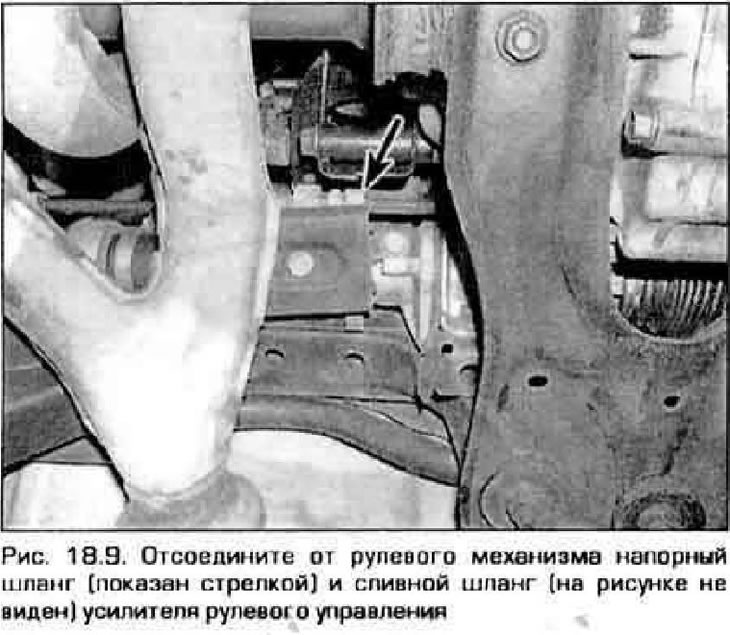
9. Place a container under the steering gear. Disconnect the pressure and drain hoses (Fig. 18.9)…


10. Inside the vehicle, remove the steering shaft universal joint cover. Mark the position of the lower section of the driveshaft relative to the pinion shaft. Remove the lower pinch bolt of the intermediate section of the steering shaft.


11. Disconnect the ground wire from the rear engine mount.

12. Remove the three bolts of the rear engine mount bracket (see chapter 2A or 2B). Remove the rear engine mount.

13. On models with a manual transmission, disconnect the support from the transmission and move it to the side (see chapter 7A).

14. Place a hydraulic jack under the center of the subframe (or place supports under the inner hinges of the suspension arms to support the subframe). While supporting the subframe, unscrew the four bolts and two nuts that secure it.

Warning: Do not be under the subframe or under the front of the vehicle when performing this operation.


15. Remove the anti-roll bar (see paragraph 6).

16. Remove the steering gear mounting bolts (figure 18.16). Disconnect the intermediate shaft from the pinion shaft, then remove the mechanism from the vehicle.
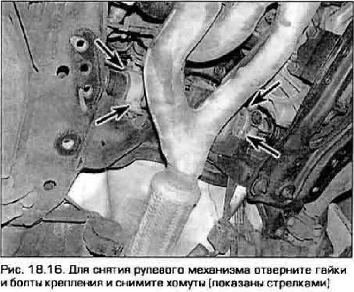
16. Remove the steering gear mounting bolts (figure 18.16). Disconnect the intermediate shaft from…


17. Inspect the steering gear rubber mounts and replace them if worn or damaged.

Installation


Note: Before installing the steering gear, set it to the center position.


18. Install the steering gear in place and connect it to the cardan joint in accordance with the marks.


19. Install the mounting brackets, insert the bolts and tighten them to the specified torque.

20. Connect the mechanism ventilation tube.

21. Install the anti-roll bar (see paragraph 6).

22. Connect the steering rod ends to the steering knuckles (see paragraph 16).

23. Insert the universal joint mounting pinch bolt and tighten it to the specified torque.

24. Connect the pressure and drain hoses to the mechanism and fill the power steering fluid reservoir with the recommended fluid (see chapter 1).

25. Installation of the remaining components is carried out in the reverse order of removal.

26. Tighten all suspension and steering component fasteners to the specified torque. Tightening torques for the cross beam and gearbox support fasteners are given at the beginning chapter 7. The tightening torque for the subframe fasteners is given at the beginning of this chapter.

27. Install the wheels, tighten the lug nuts and lower the vehicle. Tighten the wheel nuts to the specified torque (see Technical data at the beginning of Chapter 1). Bleed the air from the power steering hydraulic system (see paragraph 20).
This article is available at: russian, bulgarian, belarusian, ukrainian, serbian, croatian, romanian, polish, slovak, hungarian
This text was checked by: German Vorobyov
Share with friends on social networks:

Previous
Capella 6 » Steering
Next

Steering gear covers — replacement
Tie rod ends — removal and installation
Steering column — removal and installation
Steering wheel — removal and installation
Power steering pump — removal and installation
Hydraulic steering system — bleeding
More articles on repairing other Mazda models
Components of a mechanical steering gear with a constant gear ratio Mazda Familia 5 (1985-1989)
Technical characteristics of the steering gear Mazda3 BK (2003-2009)
Central steering column switch for exterior lighting Mazda6 GG (2002-2008)
Removal and installation the steering gear with rods Mazda CX-5KE (2012-2017)
Removal and installation rubber steering gear boots Mazda 121 (3) (1996-2003)
Link in different formats to this article
Comments and feedback from visitors
No comments yet


How much will 27 + 18 ?


Capella 6 (1997-2005, petrol) 
  • General information
  • Introduction to guide
  • User manual
  • Troubleshooting
  • Maintenance
  • Power unit
  • 4-cylinder engines
  • 6-cylinder engines
  • Engine overhaul
  • Cooling and ventilation
  • Power and exhaust systems
  • Engine electrics
  • Control system
  • Transmission
  • Mechanical gearbox
  • Automatic gearbox
  • Clutch and drive shafts
  • Chassis
  • Brake system
  • Car suspension
  • Steering
  • Body
  • Exterior (external elements)
  • Interior (internal elements)
  • Doors, windows and locks
  • Electrical equipment
  • Equipment and devices
  • Electrical circuits
Capella 5 (1991-1997) 
  • General information
  • User manual
  • Maintenance
  • Helpful hints
  • Power unit
  • Petrol engines 1.6 and 1.8
  • Petrol engines 2.0
  • 2.5 petrol engines
  • Overhaul engines 1.6 and 1.8
  • Overhaul engines 2.0 and 2.5
  • Diesel engine 2.0
  • Engine electrics
  • Cooling system
  • Air conditioner
  • Carburetor Nikki 30/34
  • Power system (1.6 and 1.8)
  • Power system (2.0 and 2.5)
  • Control system
  • Transmission
  • Mechanical gearbox
  • Automatic gearbox
  • Clutch and axles
  • Chassis
  • Brake system
  • Suspension and wheels
  • Steering
  • Body
  • Exterior (external elements)
  • Interior (internal elements)
  • Doors and windows
  • Electrical equipment
  • Equipment and devices
  • Electrical circuits
Capella 4 (1987-1992) 
  • General information
  • Introduction to manual
  • Vehicle specifications
  • Power unit
  • Engine repair
  • Lubrication system
  • Cooling system
  • Fuel system (carburetor)
  • Fuel injection (FE)
  • Fuel injection (DOHC)
  • Fuel system (diesel)
  • Ignition system
  • Transmission
  • Clutch
  • Gearbox
  • Drive shafts
  • Chassis
  • Front suspension
  • Rear suspension
  • Steering system
  • Brake system
  • Electrical equipment
  • Equipment and devices
  • Electrical circuits
Capella 3 and 4 (1982-1992) 
  • General information
  • User manual
  • Maintenance
  • Power unit
  • Gasoline engine
  • Engine overhaul (gasoline)
  • Diesel engine
  • Cooling and heating
  • Supply system
  • Ignition system
  • Emission reduction
  • Transmission
  • Clutch
  • Mechanical gearbox
  • Automatic gearbox
  • Drive shafts
  • Chassis
  • Brake system
  • Suspension and wheels
  • Steering
  • Body
  • Exterior (external elements)
  • Interior (internal elements)
  • Electrical equipment
  • Equipment and devices
  • Power devices
  • Electrical circuits
Capella 3 (1982-1992, petrol) 
  • General information
  • User manual
  • Maintenance
  • Troubleshooting
  • Late models
  • Power unit
  • Engine in car
  • Engine overhaul
  • Cooling and heating system
  • Fuel and exhaust system
  • Engine electrical system
  • Emission control system
  • Transmission
  • Mechanical gearbox
  • Automatic gearbox
  • Clutch and drive shafts
  • Chassis
  • Brake system
  • Suspension and wheels
  • Steering
  • Body
  • Exterior (external elements)
  • Interior (internal elements)
  • Electrical equipment
  • Equipment and devices
  • Lighting and lamps
  • Electrical circuits
MazBook.ru © 2018–2026 · Mobile version · Articles and news · Sitemap: EN BG BY UA RS HR RO PL SK HU · Feedback · Site search · Add to bookmarks Familia 5 (BF) · Familia 6 (BG) · Capella 3 (GC) · Capella 3 and 4 (GC) · Capella 4 (GD) · Capella 5 (GE) · Capella 6 (GF) · Mazda3 BK · Mazda6 GG · CX-5KE · Mazda 121 (3) · Mazda BT-50 (1) ·
By continuing to use the site, you agree to the use of cookies 🔐