


Contents: General checks ⇓ Checking the fuel pump operation and…⇓ Checking the fuel pump power supply…⇓ Checking the solenoid valve of the…⇓
See the warning at the beginning of paragraph 2.
Note: To check the fuel system pressure, you will need a pressure gauge that measures the operating pressure in the system and a set of adapters to connect the gauge to the system components, including the operating injectors.
General checks
1. Make sure there is fuel in the tank and that it is suitable for the engine.
2. Check the operation of the fuel pump. To do this, ask an assistant to turn on the ignition, while you stand near the fuel tank. You should hear the pump humming for about two seconds. During this time, the pump fills the pipelines and increases the pressure in the system.
Note: Pump operation can be clearly heard through the open fuel tank filler neck. If the pump does not work, go to step. 10 and check the electrical purpose of the pump power supply.
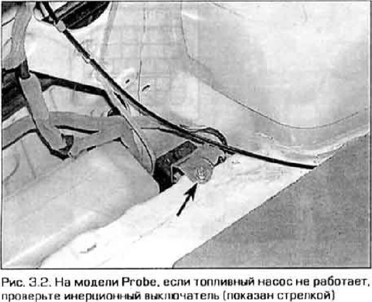
Note: On the Probe model, first check the inertia switch located in the trunk (figure 3.2). The switch blocks power to the fuel pump in the event of an accident. But it can also work by accident. for example, if something is dropped on it or from a slight collision while parking.
Checking the fuel pump operation and fuel system pressure
3. If your model has a 4-cylinder engine and cruise control, disconnect the cruise control actuator and move it to the side without disconnecting the cable or wiring.
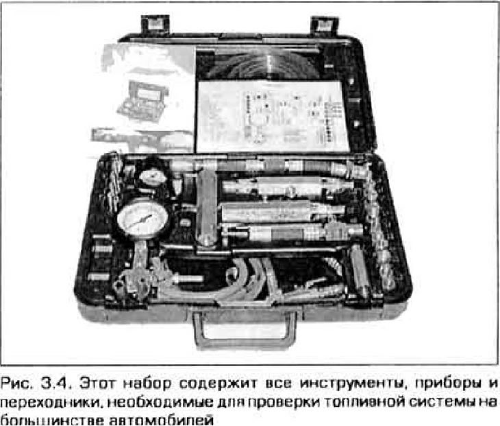
4. Connect the pressure gauge to the hose coming from the fuel filter (4-cylinder engine) or between fuel rails (V-shaped engine) (figure 3.4).
5. Turn on the ignition (do not start the engine) with the air conditioner turned off. The fuel pump will turn on for two seconds and the pressure gauge should register the pressure in the system, which should not change after that.
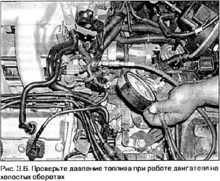
6. Start the engine, warm it up to normal operating temperature and let it idle. Compare the pressure in the system with the value given in Technical data at the beginning of the chapter (Fig. 3.6). Now disconnect the vacuum hose from the fuel pressure regulator - the pressure should increase immediately. If the pressure in the system is correct Technical data, then the system is working properly.
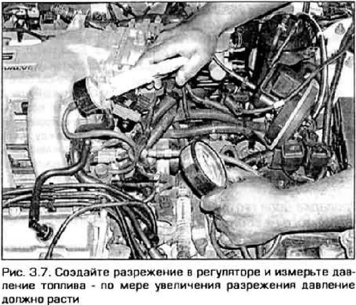
7. If the pressure does not increase when disconnecting the vacuum hose, connect a hand vacuum pump to the pressure regulator and create a vacuum in the regulator (figure 3.7). If the fuel pressure has decreased, check the vacuum supply line to the regulator (including the solenoid valve as specified below in this paragraph). If all components of the supply line are in good condition and the pressure does not drop, replace the fuel pressure regulator.
8. If the pressure shown by the pressure gauge does not correspond to the values specified in Technical data, perform the following checks.
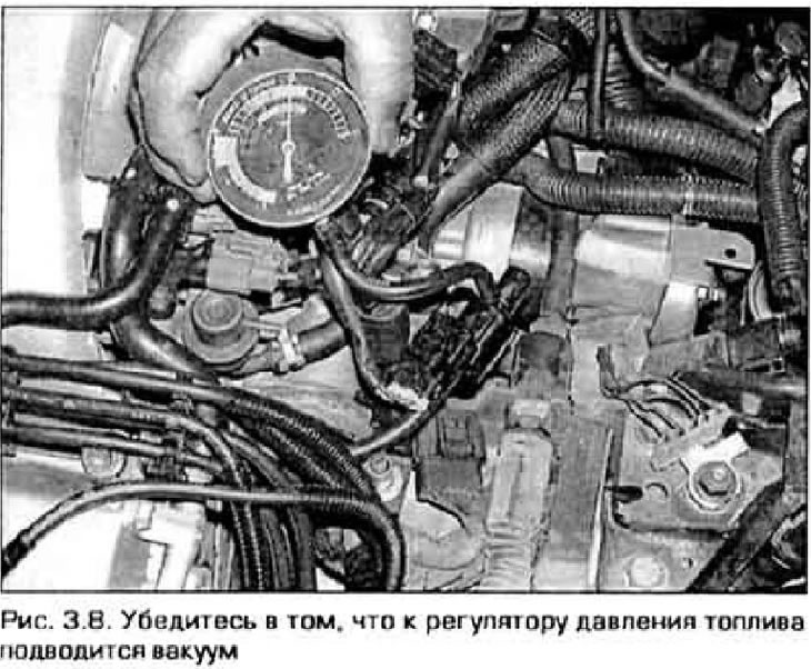
- a) If the pressure is higher than required, check if vacuum is being supplied to the regulator (figure 3.8). The vacuum in the vacuum hose should change depending on the engine speed. If there is a vacuum, check to see if the fuel return line is clogged. If the return line is in good condition. replace the regulator.
- b) If the pressure is less than required, replace the fuel filter to be sure that it is not the problem. The filter replacement procedure is described in chapter 1. Another filter - a mesh one - is located at the fuel pump inlet in the fuel tank (see paragraph 5). If the pressure is still lower than required, start the engine (if possible) and slowly squeeze the fuel return hose. If the fuel pressure increases to 3 bar, replace the regulator (paragraph 14), Caution! Do not allow the fuel pressure to exceed 4 bar.
- c) If the pressure remains low even with the return hose pinched, the cause may be a leaking injector (or injectors) (see paragraph 15). The fuel pump itself may also be faulty.
9. After checking, release the pressure in the fuel system again (see paragraph 2) and disconnect the pressure gauge.
Checking the fuel pump power supply circuit
Note: For detailed diagrams of the fuel pump power supply circuits and its relay, see. in chapter 12.
10. If the pump does not work when the ignition is turned on (does not make any sounds), check the pump fuse located in the engine compartment fuse box. If the fuse is blown, replace it and see if the pi still works. If the pump now starts working, find a short circuit in the wire from the relay to the pump.
Models produced from 1993 to 1997
(Article is based on website data: Mazbook.ru)
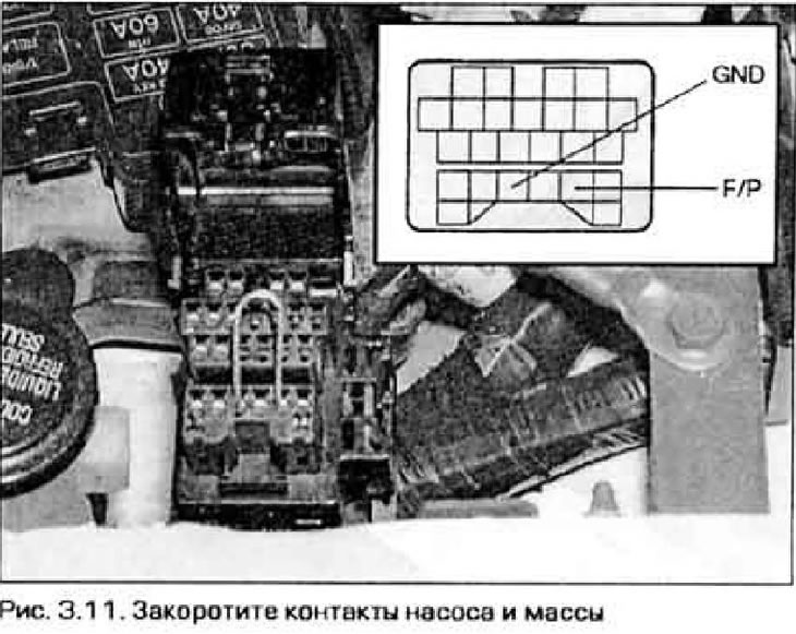
11. If the pump still does not work, remove the cover from the diagnostic connector in the engine compartment and short-circuit the fuel pump and ground contacts with a jumper wire (figure 3.11). The pump should start working.
Models produced since 1998
12. If the pump still does not work, remove the pump relay from the relay box in the engine compartment. On 1998 models for models produced since 1999, short-circuit contacts 30 and 37. For models produced since 2000, short-circuit contacts 30 and GND (ground). Be careful. Short only these contacts.
All models
13. If the pump does not work, check if there is power supplied to the pump at the connector on the fuel tank (see the wiring diagrams at the end of the manual). If there is voltage in the connector, then the circuit to the pump is working properly. Check for electrical continuity between the ground contact in the connector and the vehicle ground. If there is no connection, check the ground circuit for an open or poor contact.
14. If there is supply voltage and the grounding point is OK, replace the pump (paragraph 5).
Checking the solenoid valve of the regulator
15. This valve (not all models are equipped with it) interrupts the vacuum supply to the pressure regulator under certain engine operating conditions. Vacuum shut-off allows increasing fuel pressure and preventing vapor lock.
16. If there is no vacuum supplied to the regulator, check this valve.
17. Locate the valve by tracing the vacuum hose from the fuel pressure regulator. Disconnect the vacuum hoses from the valve (see figure 3.8).
18. Connect a piece of rubber hose to the valve inlet and blow into it. Air must pass through the valve,
19. Disconnect the electrical connector from the valve. Apply positive voltage from the battery to the positive terminal of the electromagnet, and connect the other terminal to ground. Now air should not pass through the valve.
20. If the valve does not work as described, it is faulty. Replace it.