MazBook.ru
English Русский
Български
Беларускі
Український
Српски
Hrvatski
Română
Polski
Slovenský
Magyar
• Bookmark • Sitemap • Contacts •   
Cars Opel Cars Ford Cars Volkswagen Cars Audi Cars Kia Cars Renault Cars Peugeot


Familia Capella Mazda3 Mazda6 CX-? Others Articles
Capella 3 (1982-1992, petrol) Capella 3 and 4 (1982-1992) Capella 4 (1987-1992) Capella 5 (1991-1997) Capella 6 (1997-2005, petrol)

Engine — removal and installation (Mazda Capella GC)

  • Home
  • Mazda Capella
  • Capella GC (1982-1992)
  • Power unit
  • Engine in car
  • Engine — removal and installation
0
Contents: Removal ⇓ Installation ⇓
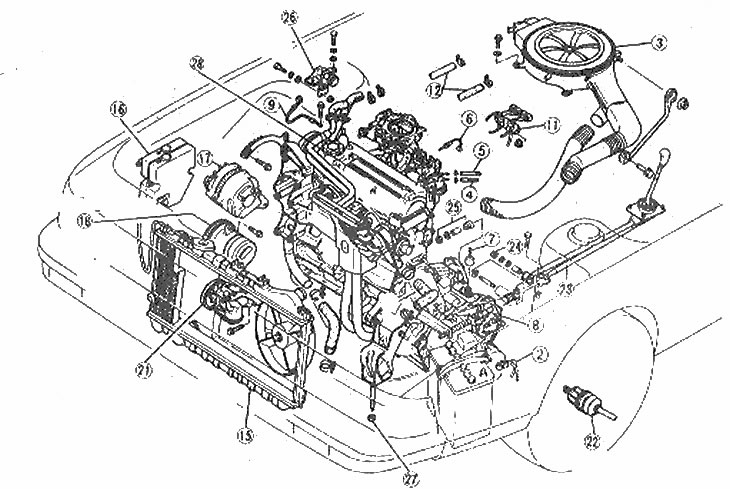
To remove the engine, the parts listed are removed in the order shown

To remove the engine, the parts listed are removed in the order shown

1. Hood (not shown); 2. Negative battery cable; 3. Air filter assembly; 4. Fuel supply hose; 5. Fuel return hose; 6. Throttle cable; 7. Speedometer drive cable; 8. Clutch cable; 9. Engine ground cable; 10. Brake booster hose (not shown); 11. Three-way steering valve; 12. Heater hoses; 13. Engine wiring to transmission (not shown); 14. Vacuum hoses of the evaporation system (not shown); 15. Fan and radiator; 16. Cooling and windshield washer reservoirs; 17. Generator; 18. Air conditioning compressor; 19. Front ears (not shown); 20. Mudguards (not shown); 21. Power steering pump; 22. Driven sluggish; 23. Manual transmission shift lever; 24. Manual transmission extension lever; 25. Soft joints of the exhaust system, fastening bolts and nuts; 26. Anti-rotation stop; 27. Engine and transmission mounting nuts (not shown); 28. Engine and transmission


See also Section 2B, Chapter 5.

Removal


1. Remove the hood (Section 11).

2. Remove the battery and its fasteners, drain the liquid from the cooling system (Section 1).


3. Remove the air filter assembly (photo).
Removing the air filter heating hose

Removing the air filter heating hose
Removing the air filter duct

Removing the air filter duct

Removing the crankcase ventilation hose from the air filter

Removing the crankcase ventilation hose from the air filter
Disconnecting the air injection hoses from the air filter

Disconnecting the air injection hoses from the air filter


Removing the bolt securing the air filter cover to the camshaft cover

Removing the bolt securing the air filter cover to the camshaft cover
Removing the bolts securing the air filter to the carburetor

Removing the bolts securing the air filter to the carburetor

4. Remove the fuel inlet and return lines from the fuel pump.

5. Disconnect the throttle cable, choke cable and cruise control cable (if equipped).

6. Disconnect the speedometer drive cable.

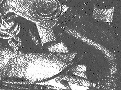
7. Disconnect the clutch cable (for manual transmission) or gear selector cable (for automatic transmission) (photo).
Remove the gear selector cable pin with pliers

Remove the gear selector cable pin with pliers


8. Disconnect the ground harness connector from the transmission.

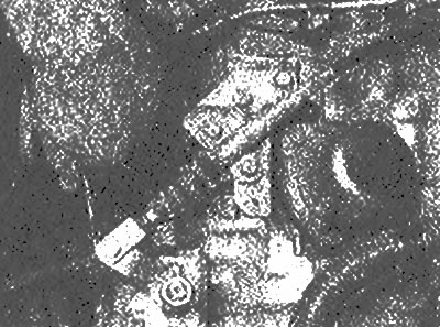
9. Disconnect the brake booster hose (photo).
Tighten the hose clamp so that you don't lose it

Tighten the hose clamp so that you don't lose it


10. Disconnect the vacuum switches and remove the bracket.

11. Disconnect the heater hoses.

12. Disconnect the traction relay and vacuum sensor (when equipped) and unscrew them from the thermal insulation shield.

13. Disconnect the wiring harnesses to the engine.

14. Disconnect any remaining electrical connectors.

The article is copied from the website [MAZBOOK]

15. Disconnect the ignition coil wire from the gel distributor.

16. Disconnect the evaporative system hoses from the tank (when equipped).

17. Disconnect the radiator hoses and turn off the fan motor.

18. Remove the radiator (Section 3).

19. Remove the coolant tanks. radiator and windshield washer fluids.

20. Remove the generator and (if equipped) air conditioner compressor from bracket. Remove the compressor, taking care not to damage the hose and (which contain high pressure) and secure it with a piece of wire.

21. Jack up the front of the car. place it on the jack stands and remove the front wheels and inner fender mudguards.


22. Remove the power steering pump (when equipped) with hoses and secure it in the engine compartment with a piece of wire.

23. Drain the transmission fluid (Section 1, Chapter 25 or 28).

24. Disconnect the front stabilizer linkages and front suspension ball joints, then pull or disconnect the inner ends of the axle shafts from the transmission or coupling shaft (photo). See. Section 8, Chapter 7. Leave the coupling shaft inserted into the transmission to secure the differential in position.
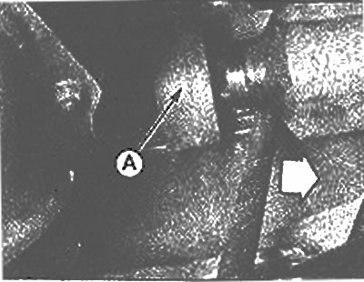
Pull the right half shaft out of the connecting shaft housing (A) in the direction of the arrow

Pull the right half shaft out of the connecting shaft housing (A) in the direction of the arrow


25. On manual transmission models, disconnect the push rod and extension lever from the transmission. If necessary, please contact Section 7, Part A, Chapter 4.

26. Disconnect the exhaust pipe from the muffler (photo).
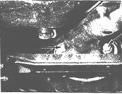
Nuts securing the exhaust pipe to the muffler (arrows)

Nuts securing the exhaust pipe to the muffler (arrows)


27. Remove the rubber plug and inner wing access shield, unscrew and remove the anti-rotation stop and drive belt covers.

28. Attach the lift to the engine.

29. Disconnect the engine mounts.

30. Slowly lift the engine and, with the help of an assistant, carefully pull the engine forward away from the muffler struts and move the wiring harnesses to the side (photo).
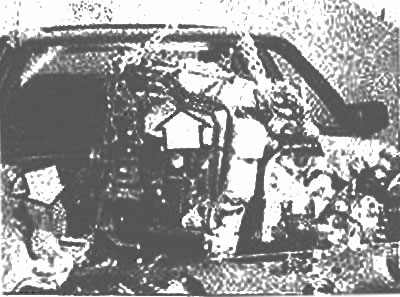
Move the engine forward and then remove it from the engine compartment (arrows)

Move the engine forward and then remove it from the engine compartment (arrows)


31. Lift the engine out of the engine compartment and lower it onto a suitable work surface. Separate the transmission from the engine (Chapter 26). Lock the engine in the raised position or install it on the stand.

Installation


32. Reconnect the engine to the transmission.

33. The front of the vehicle must remain raised to allow access from underneath during installation.

34. Place the engine directly into the engine compartment and lower it slowly and carefully into place.

35. You will need help to connect the transmission without hitting the master cylinder, then slide the engine mounts and muffler towers into place, while keeping an eye on the power steering pump to make sure it does not interfere with the engine position.

36. Assembly is carried out in reverse order, please refer to the relevant Sections for details of the drive shaft connection and front suspension connection.
This article is available at: russian, bulgarian, belarusian, ukrainian, serbian, croatian, romanian, polish, slovak, hungarian
This text was checked by: Evdokia Filimonova
Share with friends on social networks:

Previous
Capella 3 » Engine in car
Next

Engine mounts — replacement with the engine installed on the vehicle
Pallet — removal and installation
Oil radiator — removal and installation
Flywheel ring gear replacement
Flywheel/Drive Plate and Rear Cover Seal — removal and installation
Engine and transmission — separation and connection
More articles on repairing other Mazda models
Main technical characteristics of the engine Mazda Familia 5 (1985-1989)
Engine number Mazda3 BK (2003-2009)
Engine number Mazda6 GG (2002-2008)
Emergency engine start Mazda CX-5KE (2012-2017)
Starting the engine from an auxiliary battery Mazda 121 (3) (1996-2003)
Link in different formats to this article
Comments and feedback from visitors
No comments yet


How much will 27 + 22 ?


Capella 6 (1997-2005, petrol) 
  • General information
  • Introduction to guide
  • User manual
  • Troubleshooting
  • Maintenance
  • Power unit
  • 4-cylinder engines
  • 6-cylinder engines
  • Engine overhaul
  • Cooling and ventilation
  • Power and exhaust systems
  • Engine electrics
  • Control system
  • Transmission
  • Mechanical gearbox
  • Automatic gearbox
  • Clutch and drive shafts
  • Chassis
  • Brake system
  • Car suspension
  • Steering
  • Body
  • Exterior (external elements)
  • Interior (internal elements)
  • Doors, windows and locks
  • Electrical equipment
  • Equipment and devices
  • Electrical circuits
Capella 5 (1991-1997) 
  • General information
  • User manual
  • Maintenance
  • Helpful hints
  • Power unit
  • Petrol engines 1.6 and 1.8
  • Petrol engines 2.0
  • 2.5 petrol engines
  • Overhaul engines 1.6 and 1.8
  • Overhaul engines 2.0 and 2.5
  • Diesel engine 2.0
  • Engine electrics
  • Cooling system
  • Air conditioner
  • Carburetor Nikki 30/34
  • Power system (1.6 and 1.8)
  • Power system (2.0 and 2.5)
  • Control system
  • Transmission
  • Mechanical gearbox
  • Automatic gearbox
  • Clutch and axles
  • Chassis
  • Brake system
  • Suspension and wheels
  • Steering
  • Body
  • Exterior (external elements)
  • Interior (internal elements)
  • Doors and windows
  • Electrical equipment
  • Equipment and devices
  • Electrical circuits
Capella 4 (1987-1992) 
  • General information
  • Introduction to manual
  • Vehicle specifications
  • Power unit
  • Engine repair
  • Lubrication system
  • Cooling system
  • Fuel system (carburetor)
  • Fuel injection (FE)
  • Fuel injection (DOHC)
  • Fuel system (diesel)
  • Ignition system
  • Transmission
  • Clutch
  • Gearbox
  • Drive shafts
  • Chassis
  • Front suspension
  • Rear suspension
  • Steering system
  • Brake system
  • Electrical equipment
  • Equipment and devices
  • Electrical circuits
Capella 3 and 4 (1982-1992) 
  • General information
  • User manual
  • Maintenance
  • Power unit
  • Gasoline engine
  • Engine overhaul (gasoline)
  • Diesel engine
  • Cooling and heating
  • Supply system
  • Ignition system
  • Emission reduction
  • Transmission
  • Clutch
  • Mechanical gearbox
  • Automatic gearbox
  • Drive shafts
  • Chassis
  • Brake system
  • Suspension and wheels
  • Steering
  • Body
  • Exterior (external elements)
  • Interior (internal elements)
  • Electrical equipment
  • Equipment and devices
  • Power devices
  • Electrical circuits
Capella 3 (1982-1992, petrol) 
  • General information
  • User manual
  • Maintenance
  • Troubleshooting
  • Late models
  • Power unit
  • Engine in car
  • Engine overhaul
  • Cooling and heating system
  • Fuel and exhaust system
  • Engine electrical system
  • Emission control system
  • Transmission
  • Mechanical gearbox
  • Automatic gearbox
  • Clutch and drive shafts
  • Chassis
  • Brake system
  • Suspension and wheels
  • Steering
  • Body
  • Exterior (external elements)
  • Interior (internal elements)
  • Electrical equipment
  • Equipment and devices
  • Lighting and lamps
  • Electrical circuits
MazBook.ru © 2018–2026 · Mobile version · Articles and news · Sitemap: EN BG BY UA RS HR RO PL SK HU · Feedback · Site search · Add to bookmarks Familia 5 (BF) · Familia 6 (BG) · Capella 3 (GC) · Capella 3 and 4 (GC) · Capella 4 (GD) · Capella 5 (GE) · Capella 6 (GF) · Mazda3 BK · Mazda6 GG · CX-5KE · Mazda 121 (3) · Mazda BT-50 (1) ·
By continuing to use the site, you agree to the use of cookies 🔐