
Note. With installed camshafts, it is impossible to adjust the valve clearances without a special proprietary tool. At the time of this writing, this tool was only available from the vehicle manufacturer. We tried to make a similar device in our workshop, but the attempt was not successful due to too small gaps in the fit of the pushers. However. since checking and adjusting the gaps according to the service schedule coincides with the replacement of the timing belt, the car owner can adjust the gaps without any tools by removing the camshafts until a new timing belt is installed.
1. Disconnect the negative cable from the battery.
Warning. If your car is equipped with an anti-theft audio system, before disconnecting the battery, make sure that you know the unlock code for the system after turning it on again.
2. On a 4-cylinder model, remove anything that prevents the valve cover from being removed (see chapter 2A).
3. On a V-engine model, remove the air inlet and anything that prevents the valve cover from being removed (see chapter 2B).
4. Blow off dust and dirt from the valve cover with compressed air, then remove the spark plugs (see paragraph 19).
5. Remove the cover (And) valve mechanism (see chapters 2A, 2B)
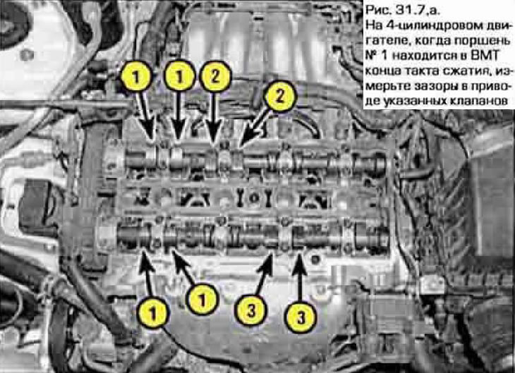
6. Set piston #1 to TDC on the compression stroke (see chapters 2A or 2B).
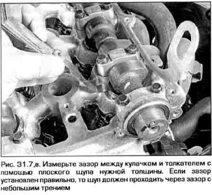
7. Measure the gaps in the valve drive with a feeler gauge, as shown in fig. 31.7, a-c. Write down the values of the gaps that do not correspond Technical Data. These values will be required in the future to select the thickness of the shims.
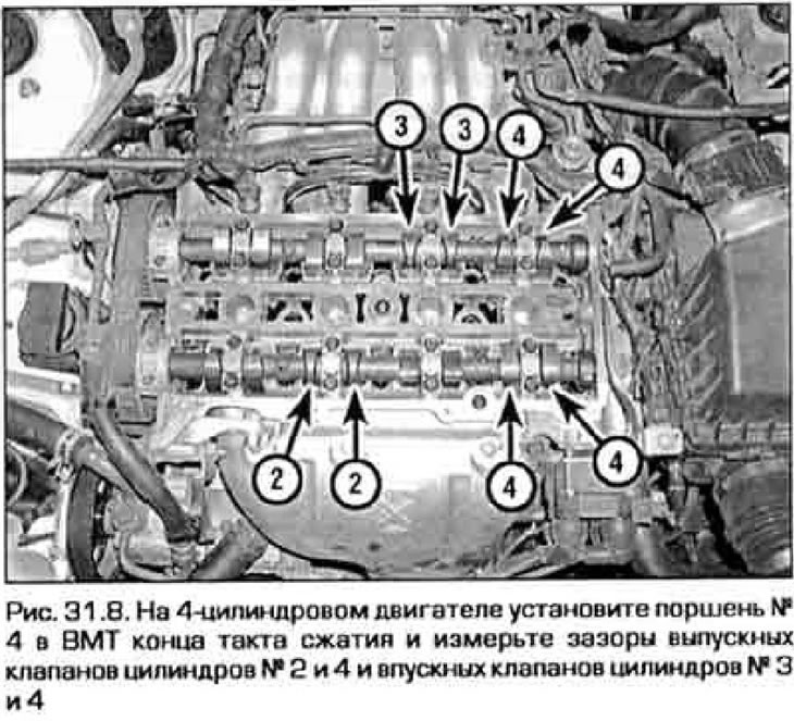
8. On a 4-cylinder engine, rotate the crankshaft a full turn and align the marks again. Measure clearances in other valves (pic. 31.8).
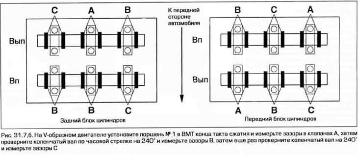
9. On a V-shaped engine, turn the crankshaft clockwise 2/3 of a turn (270°) and measure the valve clearances marked. The letter B in Fig. 31.7.6. Then turn the crankshaft another 2/3 of a turn and measure the valve clearances C.
10. If all clearances are within tolerance, reinstall all removed parts. If the clearances of some valves need adjustment, then the car owner is recommended to combine this adjustment with the replacement of the toothed belt. If the belt is in good condition and is not supposed to be changed, then a special tool will be required to adjust the valves. Both adjustment methods are described below.
Adjustment with toothed belt removed
11. Remove a gear belt and camshafts, as it is specified in the chapter 2A or 2B.
12. Remove shims one at a time from all pushers where the wrong gap is registered. Measure the thickness of each spacer and calculate the required thickness as indicated in paragraphs below. 17 and 18.
13. Insert the shims of the correct thickness, then refit the camshafts and their bearing caps by tightening their fastening bolts to the torque specified in the Technical Data chapter 2A or 2B.
14. Again measure backlashes in valves, as it is specified in pp. 6 to 10. If the clearances are correct, install the toothed belt and complete the engine assembly (in reverse order of disassembly). If not all gaps are set correctly, remove the camshafts and repeat the steps written off in paragraphs. 12 and 13.
Adjustment without removing toothed belt
Note. This version of the operation requires the use of a special device.
15. Rotate the crankshaft so that the cam of the valve you are about to adjust is facing up and away from the gasket being replaced.
16. Turn a pusher a cut-out towards a candle. Then press the pusher with the tool down. The fixture is a plate that is bolted to the camshaft bearing caps. A screw clamp is fixed on the plate, which is located above the pusher, and with which the pusher can be pressed down, thus releasing the shim. On a V-shaped engine, unscrew the inner bolts of the extreme covers of the camshafts (except for the large stop cover). On a 4-cylinder engine, remove the internal bolts of those covers between which the adjustable valve is located. Fasten the tool with long bolts over the covers so that the tool clamp is over the adjustable valve, depress the valve lifter with the tool clamp and push the adjusting washer from the top side of the tappet towards the spark plug with a small screwdriver, magnet or tweezers.
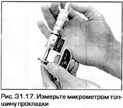
17. Measure the gasket thickness with a micrometer (pic. 31.17). To calculate the thickness of the gasket that will provide the desired clearance, use the formula:
N=T+ (A-V)
where T is the thickness of the old gasket;
A - measured gap;
N is the thickness of the new gasket;
V - required clearance (see technical data at the beginning of the chapter).
18. Pick up a gasket with a thickness closest to the calculated one. Gaskets are available in spare parts in 17 sizes with a pitch of 005 mm in the range from 2.5 mm to 3.3 mm.
Note. It is often possible to simply move the gasket from one valve where it does not provide adequate clearance to another valve. Thus, a careful analysis of the thickness of the required and available gaskets allows you to reduce the number of purchased parts.
19. After selecting the desired gasket, press the pusher again and insert the gasket into its end face. Check the gap to make sure the gasket is properly sized and installed.
20. Repeat these steps for all valves that require clearance adjustment.
21. Installation of candles, valve covers, high-voltage wires, etc. is carried out in the reverse order of their removal.