High voltage wires
1. When installing new candles, it is recommended to check the high-voltage wires.
2. Start by inspecting the wires while the engine is running. In a darkened garage (make sure it is well ventilated) start the engine and inspect each high voltage wire. Be careful not to touch the rotating parts of the engine. If the high-voltage wire has a break or an insulation defect, you will see a spark or ground breakdown in the damaged area. If such sparking is noticed, replace the corresponding wire. After checking the wires, stop the engine and let it cool down. After that check up a cover and a rotor of the distributor of ignition.
3. Now check all the wires in turn. In order not to confuse the wires in the future, number them,
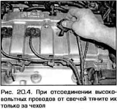
4. Disconnect the wire tip from the spark plug. To do this, you can use a special tool, or pull the tip off the candle, grabbing the rubber tip cover (pic. 20.4). Don't pull on the wire. On a V-shaped engine, access to the rear candles is especially difficult and a special tool is still needed to remove the high-voltage wires.
5. Inspect the wire sheaths for corrosion, which appears as a white fluffy powder. Minor corrosion can be removed with a wire brush, but if corrosion is significant, the wire must be replaced.
6. Put the tip of the wire on the candle. It should sit tightly on the contact of the candle. If the contact is not tight, remove the wire and press the metal petals of the tip inside the case.
7. Wipe the wire with a clean cloth along the entire length. Inspect the wire for burns, cracks, or other damage. Do not bend the wire at a sharp angle, as this may break the inner conductor.
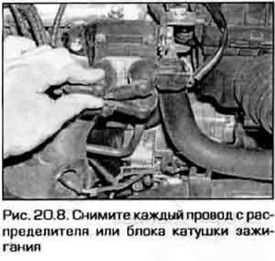
8. Disconnect the wire from the distributor or from the ignition coil unit (on models without distributor) (pic. 20.8). Pull only on the cover, not on the wire. Check for corrosion and good contact. Reconnect the wire.
9. In the same way, check the remaining high-voltage wires. At the end of all checks, the wires must have reliable contact with the candles and with the distributor (or ignition coil unit).
10. If the wires need to be replaced, purchase a wire set designed for your engine model. Replace the wires one at a time so as not to mix up the firing order.
Ignition distributor cover and rotor
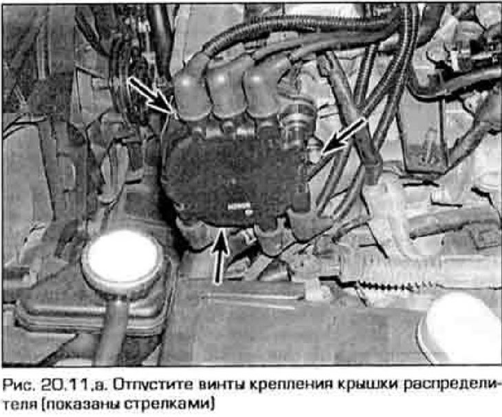
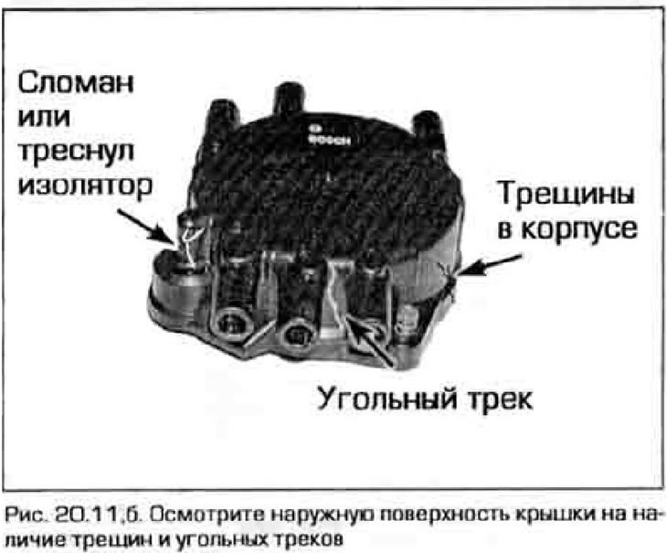
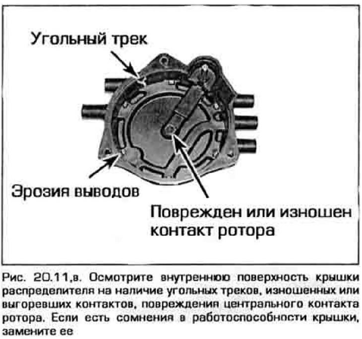
11. Remove the distributor cover by loosening its fastening screws (fig 20.11,a). Inspect the cover for cracks, carbon tracks, worn burnt or loose contacts (pic. 20.11, b, c).
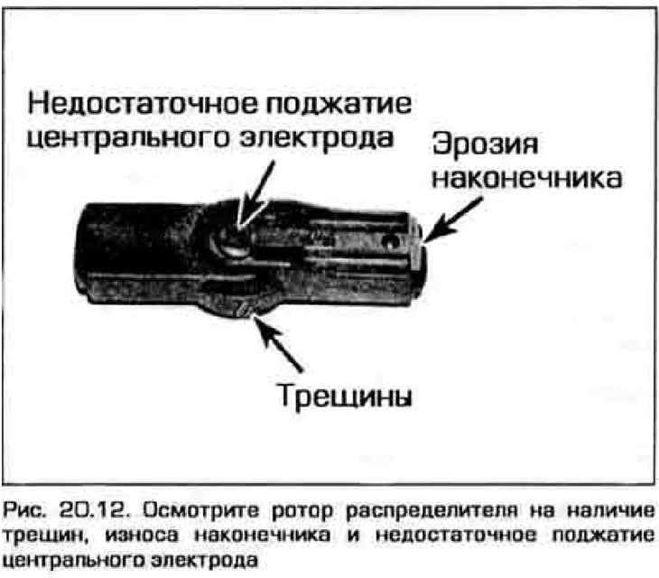
12. Remove the distributor rotor from the shaft and inspect it for cracks and carbon tracks (pic. 20.12). Replace rotor if damaged.
13. It is customary to replace the cover and distributor rotor at the same time as replacing the high voltage wires, but if you want to keep using the old distributor cover, check the resistance between the high voltage wires and the cover. If the resistance is higher than the maximum allowable value given in the Technical data for this chapter, the cover and wires must be replaced.
14. When replacing the distributor cap, disconnect the high-voltage wires one at a time from the old cap and immediately connect them to the new cap so as not to knock down the ignition order.
Note. If an accidental error occurs and the wires are reversed, use the instructions in Technical Data order of operation of the cylinders.. On most models, the #1 spark plug wire terminal on the distributor cap is marked.
Ignition coil unit (models without distributor)
15. Wipe the coil unit with a damp and then dry cloth.
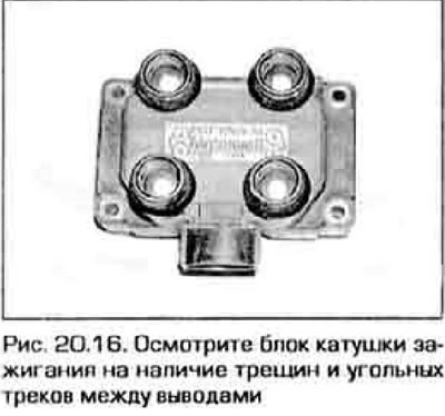
16. Inspect block for cracks, damage and carbon tracks (pic. 20.16). Charcoal tracks can usually be erased. If the block is damaged, replace it as directed in chapter 5.